Steering gear – removal and installation
Warning: DO NOT allow the steering column shaft to rotate with the steering gear removed or damage to the airbag system could occur.
1. Loosen the front wheel lug nuts, raise the front of the vehicle and support it securely on jackstands. Apply the parking brake. Remove the wheels.
2. Remove the skid plate, if equipped.
Models with hydraulic rack-and-pinion steering gear
3. Remove the intermediate shaft coupler pinch bolt and discard it (see illustration). It should be replaced with a new one according to the manufacturer.
20.3 Remove the pinch bolt from the lower end of the intermediate shaft coupler (B), then unscrew the pressure and return line fittings from the power steering gear (A)
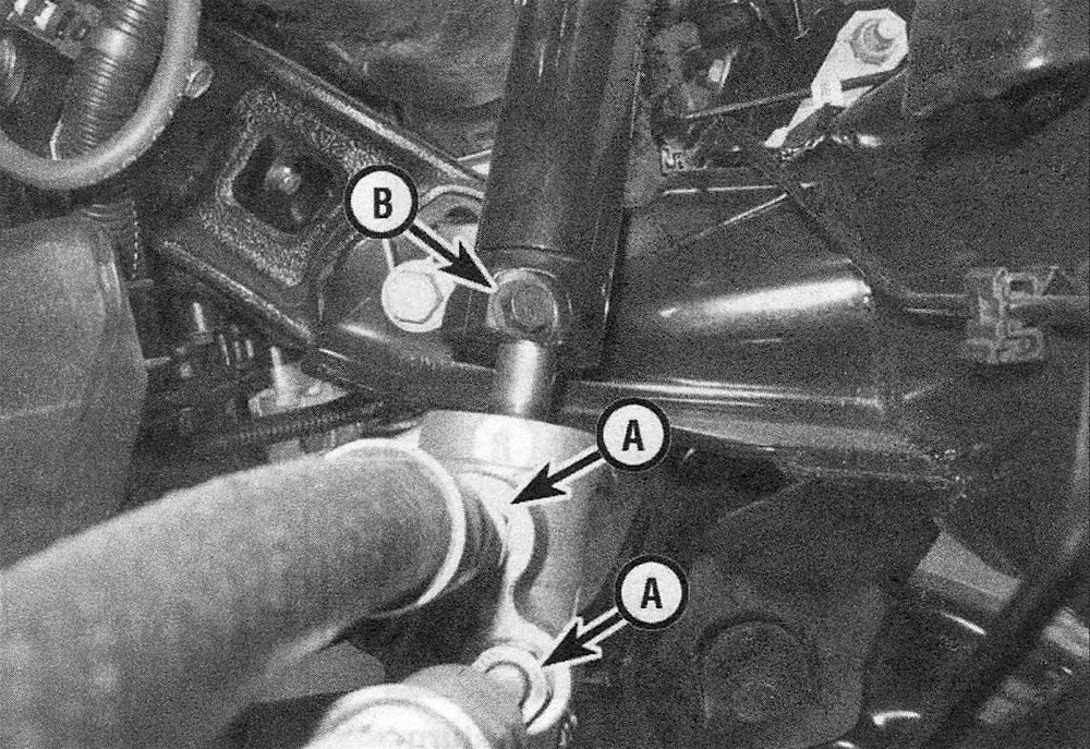
4. Position a drain pan under the steering gear. Using a flare-nut wrench, unscrew the power steering pressure and return lines from the steering gear. Cap the lines to prevent leakage.
5. Detach the tie-rod ends from the steering knuckles (Steering linkage – removal and installation).
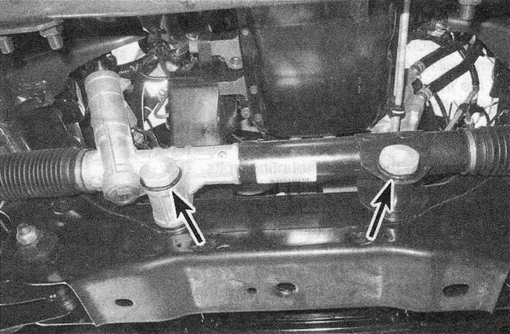
6. Unscrew the mounting bolts, then lower the steering gear from the vehicle (see illus tration).
20.6 Location of the rack-and-pinion steering gear mounting bolts
7. Installation is the reverse of removal, noting the following points:
a) Tighten the steering gear mounting bolts and the intermediate shaft coupler pinch bolt to the torque values listed in this Chapter’s Specifications.
b) Tighten the wheel lug nuts to the torque listed in the Tune-up and routine maintenance Specifications.
c) Check the power steering fluid level and add some, if necessary (see Tune-up and routine maintenance), then bleed the system (Power steering system – bleeding).
d) Re-check the power steering fluid level.
Models with Electric Power Steering (EPS) rack-and-pinion steering gear
Note: The steering column on these vehicles may not be equipped with an internal locking shaft that allows the ignition key cylinder to be locked with the key. You will have to secure and prevent the steering wheel from turning during servicing of the steering gear.
8. Disconnect the cable from the negative battery terminal (see Engine electrical systems).
9. Remove the intermediate shaft coupler pinch bolt and discard it. It should be replaced with a new one according to the manufacturer.
10. Disconnect the EPS electrical connector at the steering gear.
11. Detach the tie-rod ends from the steering knuckles (Steering linkage – removal and installation).
12. Remove the steering gear mounting bolts and slide the gear out from under the stabilizer bar.
13. Installation is the reverse of removal.
14. Once the unit is installed, reconnect the battery (see Engine electrical systems), then insert the ignition key and turn the key to the Run position. Wait approximately 8 to 10 seconds then turn the key to the Off position. Complete the calibration procedure by turning the key to the Run position again and check for trouble codes. If no codes are present, the calibration is complete.
Models with recirculating ball steering gear
15. Raise the front of the vehicle and support it securely on jackstands. Apply the parking brake.
16. Lock the steering wheel in place, using the internal mechanism or by tying it with a cord.
17. Remove the intermediate shaft coupler pinch bolt and discard it. According to the manufacturer, it should be replaced with a new one.
18. Position a drain pan under the steering gear, then unscrew the power steering lines from the steering gear. Cap the lines to prevent leakage.
19. Separate the drag link from the Pitman arm (Steering linkage – removal and installation).
20. Remove the steering gear retaining bolts from the frame rail, then detach the steering gear from the frame and remove it.
21. If you’re installing a new steering gear or a new Pitman arm, remove the Pitman arm from the steering gear sector shaft (Steering linkage – removal and installation).
22. Installation is the reverse of removal, noting the following points:
a) Tighten the steering gear mounting bolts and the intermediate shaft coupler pinch bolt to the torque values listed in this Chapter’s Specifications.
b) Tighten the wheel lug nuts to the torque listed in the Tune-up and routine maintenance Specifications.
c) Check the power steering fluid level and add some, if necessary (see Tune-up and routine maintenance), then bleed the system (Power steering system – bleeding).
d) Re-check the power steering fluid.