Shock absorber (front) – removal and installation
1. Loosen the wheel lug nuts. If you’re working on a 4WD model with independent front suspension, also loosen the driveaxle/ hub nut (see Clutch and driveline).
2. Support the outer end of the lower control arm with a floor jack (the shock absorber serves as the down-stop for the suspension). The jack must remain in this position throughout the entire procedure.
2WD models
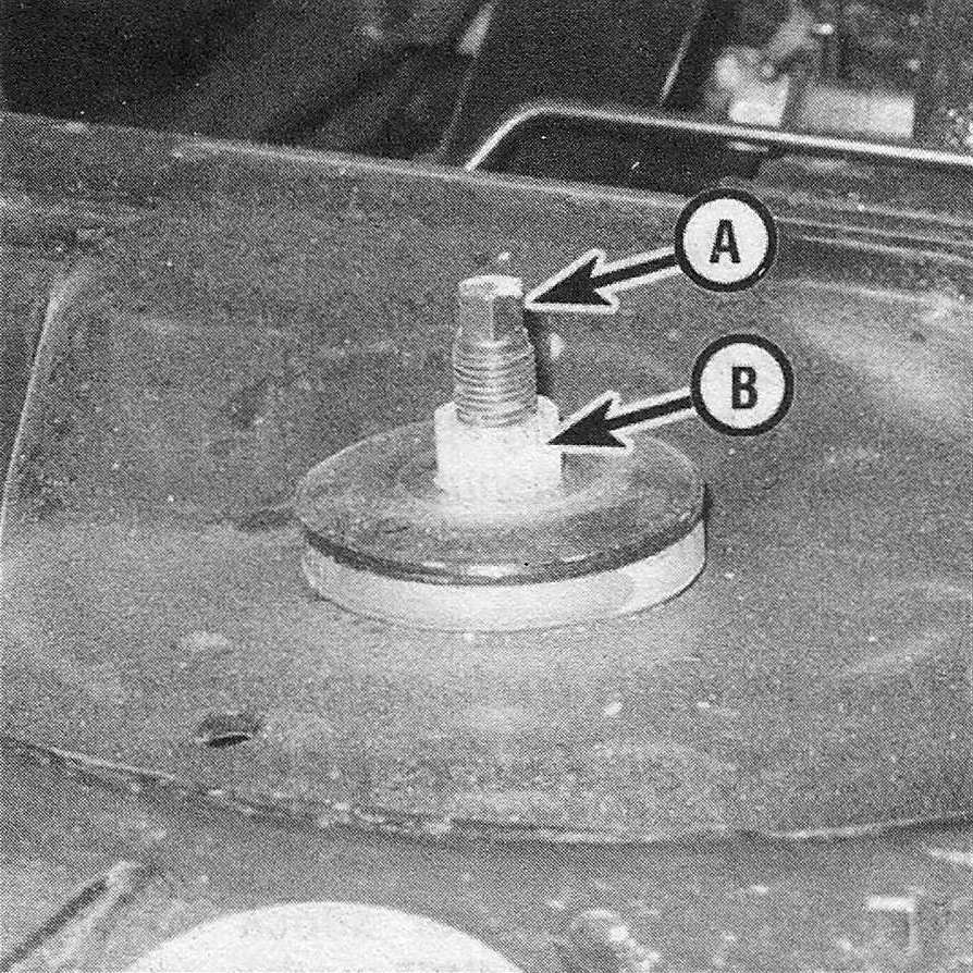
3. Using a back-up wrench on the stem to prevent it from turning, remove the shock absorber upper mounting nut (see illustration).
2.3 Hold the shock absorber stem (A) with a wrench to prevent it from turning while loosening the upper ounting nut (B)
4. Remove the retainer (metal washer) and grommet (rubber washer).
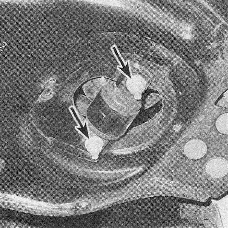
5. Working underneath the vehicle, remove the two nuts that attach the lower end of the shock absorber to the lower control arm (see illustration) and pull the shock out from below.
2.5 Shock absorber lower mounting nuts (2WD model)
6. Remove the lower grommet and retainer from the stem.
7. Before installing the shock absorber upper mounting nut, apply a thread locking compound to the threads of the shock absorber stud, then tighten the upper mounting nut and the lower mounting nuts to the torque listed in this Chapter’s Specifications.
2500/3500 4WD models
8. Using a back-up wrench on the stem, remove the shock absorber upper mounting nut. On 4WD models with a solid front axle, remove the three nuts and take off the shock absorber upper mounting bracket.
9. Remove the shock absorber lower mounting bolt.
10. Remove the shock absorber.
1500 4WD models
11. Loosen the driveaxle/hub nut. Loosen the front wheel lug nuts. Raise the front of the vehicle and support it securely on jackstands, then remove the wheel.
12. Remove the three upper shock absorber mounting nuts.
13. Remove the lower shock absorber mounting nut and bolt.
14. Remove the brake caliper and disc (see Brakes).
15. Detach the wheel speed sensor from the steering knuckle and upper control arm (if equipped).
16. Detach the upper balljoint from the steering knuckle (Balljoints – replacement).
17. Detach the stabilizer link from the lower control arm (Stabilizer bar (front) – removal and installation).
18. Remove the driveaxle/hub nut, then pull the top of the knuckle out. Remove the shock absorber/coil spring assembly.
Warning: A special tool is necessary to compress the coil spring to remove it from the shock absorber. Because of this and the safety concerns involved with this procedure, we recommend that a professional repair shop remove the coil spring from the shock absorber and install it onto the replacement shock absorber.
All models
19. Installation is the reverse of removal. Tighten all fasteners to the torque listed in this Chapter’s Specifications. On 1500 4WD models, tighten the brake caliper mounting bolts to the torque listed in the Chapter Brakes Specifications. Tighten the driveaxle/hub nut to the torque listed in the Chapter Clutch and driveline Specifications.
20. Install the wheels and lug nuts, lower the vehicle and tighten the lug nuts to the torque listed in the Tune-up and routine maintenance Specifications.