Lower control arm (front) – removal and installation
Note: This procedure applies to models equipped with independent front suspension.
2WD models
Removal
1. Loosen the wheel lug nuts, raise the vehicle and support it securely on jackstands placed under the frame rails. Remove the wheel.
2. Support the outer end of the lower control arm with a floor jack. Remove the shock absorber (Shock absorber (front) – removal and installation).
3. Remove the brake caliper, caliper bracket and disc (see Brakes).
4. Install a suitable internal type spring compressor in accordance with the tool manufacturer’s instructions (see illustration 5.3). Compress the spring sufficiently to relieve all force from the upper spring seat. This can be verified by wiggling the spring.
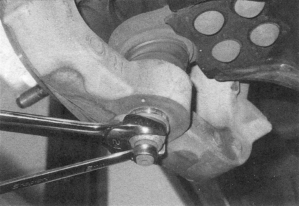
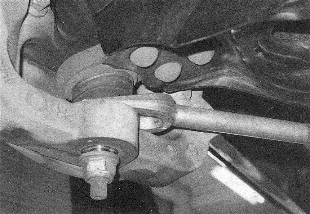
5. Loosen (but don’t remove) the nut on the lower balljoint stud (see illustration), then disconnect the balljoint from the steering knuckle with a balljoint removal tool. Note: If you don’t have the proper balljoint removal tool, a picklefork type balljoint separator can be used, but keep in mind that this type of tool will probably destroy the balljoint boot (see illustration).
7.5a If the balljoint spins when loosening the nut, hold the exposed stud with a wrench
7.5b Separating the lower control arm balljoint with a picklefork type balljoint separator
6. Disconnect the link from the stabilizer bar.
7. Lift the knuckle and hub assembly up, then place a block of wood between the upper control arm and the frame to support the assembly out of the way.
8. Pull the lower control arm down, then guide the compressed coil spring out.
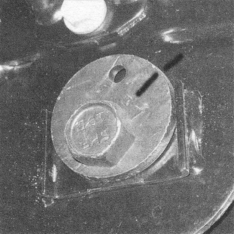
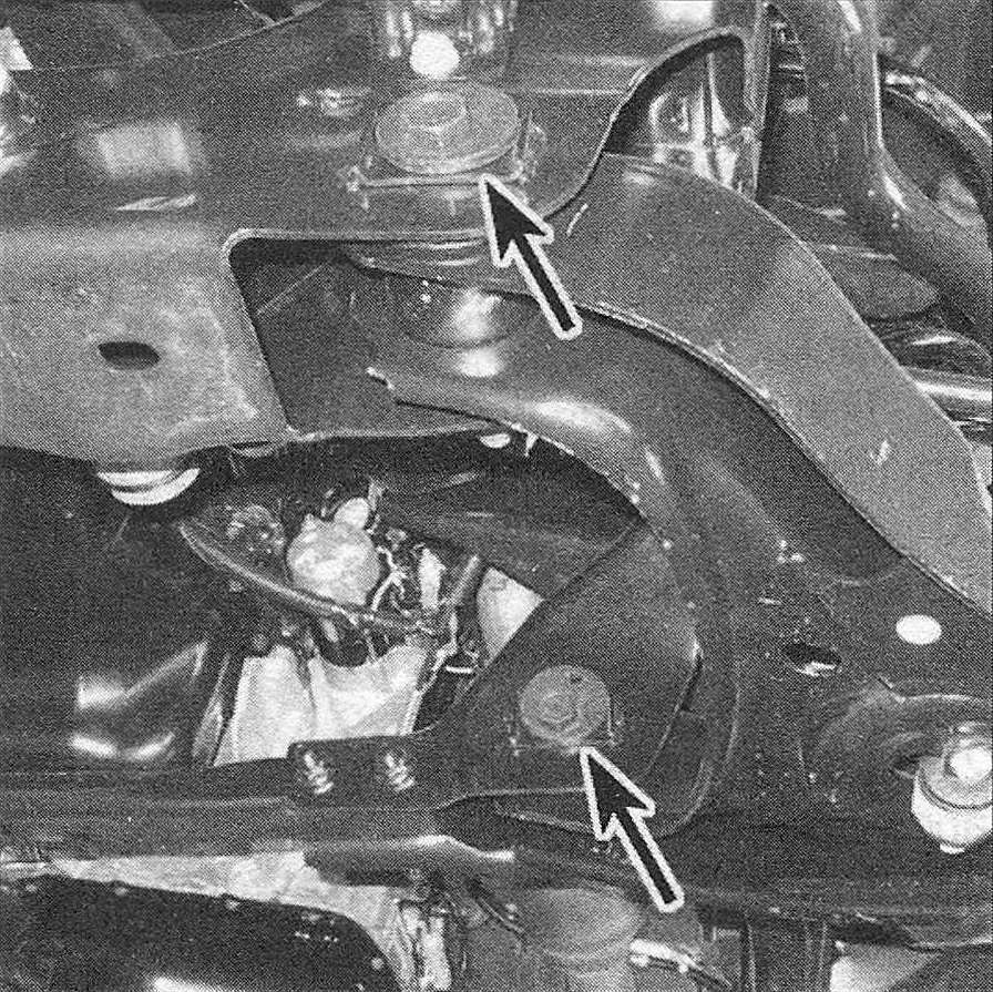
9. Mark the positions of the eccentric washers so they can be installed in the same positions (see illustration). Remove the bolts that attach the control arm to the frame (see illustration). Pull the lower arm from its frame brackets.
7.9a Mark the positions of these alignment washers, as they must be installed in the same positions (unless you’re going to have the front aligned later)
7.9b Lower control arm pivot bolts (2WD 1500 model)
Installation
10. Installation is the reverse of removal. Tighten all fasteners to the torque values listed in this Chapter’s Specifications, but don’t tighten the pivot bolt nuts until the vehicle is sitting at normal ride height. If it’s too hard to get to the nuts with the wheel on, normal ride height can be simulated by raising the outer end of the lower control arm with a floor jack.
11. Install the wheel and lug nuts. Lower the vehicle and tighten the lug nuts to the torque listed in the Tune-up and routine maintenance Specifications. Have the front end alignment checked and, if necessary, adjusted.
4WD models
Removal
12. Loosen the wheel lug nuts, raise the vehicle and support it securely on jackstands placed under the frame rails. Remove the wheel.
13. Remove the driveaxle (see Clutch and driveline), then reinstall the upper balljoint back into the steering knuckle and install the nut temporarily.
14. Disconnect the stabilizer bar from the lower control arm (Stabilizer bar (front) – removal and installation).
15. Remove the lower shock absorber bolt (Shock absorber (front) – removal and installation).
16. Loosen (but don’t remove) the nut on the lower balljoint stud a few turns, then disconnect the balljoint from the steering knuckle arm with a balljoint removal tool. Now remove the nut. Note: If you don’t have the proper balljoint removal tool, a picklefork type balljoint separator can be used, but keep in mind that this type of tool will probably destroy the balljoint boot (see illustration 7.5a).
17. Remove the lower control arm pivot bolts and pull the lower arm from its frame brackets.
Installation
18. Installation is the reverse of removal. Tighten all fasteners to the torque values listed in this Chapter’s Specifications, but don’t tighten the pivot bolt nuts until the vehicle is sitting at normal ride height. If it’s too hard to get to the nuts with the wheel on, normal ride height can be simulated by raising the outer end of the lower control arm with a floor jack.