Coil spring (front) – removal and installation
Warning: Removing a coil spring is potentially dangerous and utmost attention must be directed to the job or serious injury may result. Use only a high-quality spring compressor and carefully follow the manufacturer’s instructions furnished with it.
Models with independent front suspension (except 1500 4WD models)
Warning: On coil-over shock absorber assemblies found on 4WD models with independent front suspension, a special tool is necessary to compress the coil spring to remove it from the shock absorber (with the shock absorber assembly removed from the vehicle). Because of this and the safety concerns involved with this procedure, we recommend that a professional repair shop remove the coil spring from the shock absorber and install it onto the replacement shock absorber. See Shock absorber (front) – removal and installationto remove the shock absorber/ coil spring assembly.
Removal
1. Loosen the wheel lug nuts, raise the vehicle and support it securely on jackstands placed under the frame rails. Remove the wheel.
2. Support the outer end of the lower control arm with a floor jack. Remove the shock absorber (Shock absorber (front) – removal and installation).
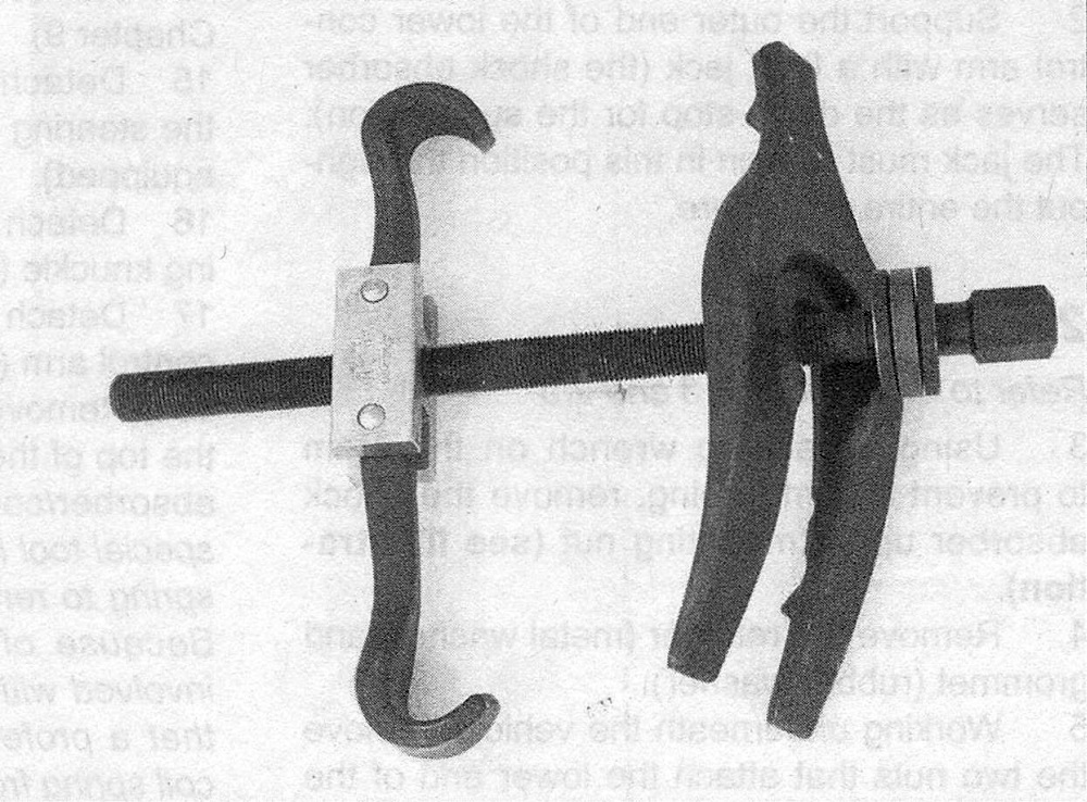
3. Install a suitable internal-type spring compressor in accordance with the tool manufacturer’s instructions (see illustration). Compress the spring sufficiently to relieve all pressure from the upper spring seat. This can be verified by wiggling the spring.
5.3 A typical aftermarket internal spring compressor tool: the hooked arms grip the upper coils of the spring, the plate is inserted below the lower coil, and when the threaded rod is turned, the spring is compressed
4. Disconnect the stabilizer bar link from the lower control arm (Stabilizer bar (front) – removal and installation).
5. Separate the lower control arm from the steering knuckle; loosen the lower balljoint nut a few turns (don’t remove it), install a balljoint separator and break the balljoint loose from the knuckle. Now remove the nut. Note: If you don’t have the proper balljoint removal tool, a picklefork type balljoint separator can be used, but keep in mind that this type of tool will probably destroy the balljoint boot.
6. Lift the knuckle and hub assembly up, then place a block of wood between the upper control arm and the frame to support the assembly out of the way.
7. Lower the floor jack, then guide the compressed coil spring out.
Installation
8. Place the insulator on top of the coil spring (the upper end of the spring is the end with the more tightly wound coils).
9. Install the top of the spring into the spring pocket and the bottom in the lower control arm.
10. Connect the lower control arm to the steering knuckle (Lower control arm (front) – removal and installation). Remove the spring compressor.
11. The remainder of installation is the reverse of removal. Tighten all fasteners to the proper torque values. Tighten the wheel lug nuts to the torque listed in the Tune-up and routine maintenance Specifications.
12. Have the front end alignment checked and, if necessary, adjusted.
Models with a solid front axle
13. Loosen the front wheel lug nuts, raise the front of the vehicle and support it securely on jackstands placed under the frame rails. Remove the wheels.
14. Use floor jacks to support the end of the axle from which you’re removing the spring.
15. Install a coil spring compressor on the coil spring and compress the spring slightly (this is to make sure it won’t slip, fall off or fly out).
16. Remove the upper suspension arm and loosen the lower suspension arm nuts and pivot bolts (Suspension arms (front) (link/coil suspension) – removal and installation).
17. Mark and disconnect the front driveshaft from the front axle (see Clutch and driveline).
18. Disconnect the track bar from the frame rail bracket.
19. Disconnect the drag link from the Pitman arm (Steering linkage – removal and installation).
20. Disconnect the stabilizer bar link from the axle (Stabilizer bar (front) – removal and installation).
21. Disconnect the shock absorber from the axle (Shock absorber (front) – removal and installation).
22. Lower the axle until the coil spring is free and remove the spring.
23. Installation is the reverse of removal.