Transmission – removal and installation
Removal
1. Disconnect the cable (s) from the negative battery terminal(s) (see Engine electrical systems).
2. Put the transmission shift lever into the NEUTRAL position.
3. Remove the shift tower and lever assembly (Shift lever – removal and installation).
4. Raise the vehicle and support it securely on jackstands.
5. Remove the skid plate, if equipped.
6. Disconnect the electrical connector from the back-up light switch and detach the wiring harness from any clips on the transmission
7. Drain the transmission lubricant (see Tune-up and routine maintenance).
8. Remove the driveshaft (see Clutch and driveline). Mark the flange and the driveshaft so it can be installed in the same position. Repeat the procedure for the front driveshaft on 4WD models.
9. On 4WD models, remove the transfer case shift linkage, then remove the transfer case (see Transfer case). Caution: Don’t allow the release lever plunger to tilt or become angled in its bore. This can cause oil leakage.
10. Detach the clutch release cylinder from the clutch housing (see Clutch and driveline), then move the cylinder aside for clearance. If you’re careful, you should be able to set the release cylinder aside without actually disconnecting the clutch hydraulic line from the release cylinder.
11. On Hemi engines, remove the starter motor (see Engine electrical systems).
12. On Hemi engines, remove the structural dust cover. Note: Don’t remove the dust cover from the engine block to avoid having to align it and the clutch housing with the engine.
13. On diesel models, remove the interfering exhaust bracket.
14. Remove the exhaust pipe if it interferes with removal.
15. Support the engine from above with an engine hoist, or place a jack (with a block of wood as an insulator) under the engine oil pan. The engine must remain supported at all times while the transmission is out of the vehicle.
16. Support the transmission with a transmission jack (available at auto parts stores and at tool rental yards) or with a large heavy-duty floor jack. If you’re going to use a floor jack to support the transmission, make sure that you use a transmission jack adapter head (also available at auto parts stores and at tool rental yards). These transmissions are very heavy, so it’s a good idea to have someone help you lower the transmission to make sure that it doesn’t fall off the jack.
17. Raise the transmission slightly, then disconnect and remove the transmission mount between the extension housing and the crossmember.
18. Remove the bolts and nuts attaching the crossmember to the frame rails, then remove the crossmember.
19. After the crossmember has been removed, lower the jack slightly so that the transmission is still supported but neither raised nor lowered by the jack.
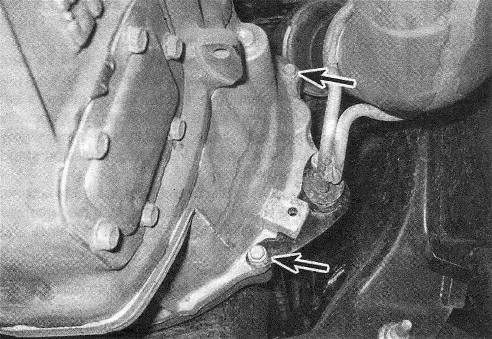
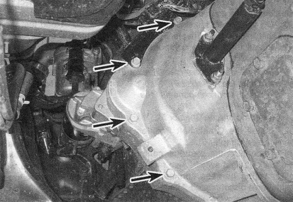
20. Remove the bolts attaching the transmission to the engine (see illustrations).
5.20a Right-side transmission mounting bolts (not all bolts are visible in this photo)
5.20b Left-side transmission mounting bolts (not all bolts are visible in this photo; the two center bolts are the starter mounting bolts, which will already have been removed)
21. Make a final inspection for any wiring harness or hoses that might still be connected to the transmission.
22. Keeping the transmission level, roll the jack toward the rear of the vehicle until the transmission input shaft clears the splined hub in the clutch disc.
23. Once the input shaft is clear, lower the transmission to the floor and remove it from under the vehicle.
24. While the transmission is removed, be sure to remove and inspect all clutch components (see Clutch and driveline). Always install new clutch components anytime that you have to remove the transmission.
Installation
25. Apply a light coat of high-temperature bearing grease (or a suitable equivalent) to the following components:
Pilot bearing (in the rear end of the crankshaft)
Driveshaft slip yoke
Input shaft splines
Release bearing bore
Release bearing sliding surface
Release fork ballstud
After lubricating the above components, install the clutch components (see Clutch and driveline).
26. Raise the transmission into position and carefully slide it forward, engaging the input shaft with the clutch plate hub. Do not use excessive force to install the transmission – if the input shaft does not slide into place, readjust the angle of the transmission so it is level and/or turn the input shaft so the splines engage properly with the clutch.
27. Install the transmission-to-engine bolts and tighten them to the torque listed in this Chapter’s Specifications. Caution: Don’t use the bolts to draw the transmission to the engine. If the transmission doesn’t slide forward easily and mate with the engine block, find out why before proceeding.
28. Raise the transmission extension housing just high enough to clear the crossmember, install the crossmember and attach it to the frame rails. Install the transmission mount between the extension housing and the crossmember. Carefully lower the transmission extension housing onto the mount and the crossmember. When everything is properly aligned, tighten all nuts and bolts securely.
29. Remove the jacks supporting the transmission and the engine.
30. On 4WD models, install the transfer case and shift linkage (see Transfer case).
31. Install the various components previously removed:
Clutch release cylinderYsee Clutch and driveline)
Driveshaft (see Clutch and driveline)
Exhaust system components (see Chapter Fuel and exhaust systems – gasoline engines Fuel and exhaust systems – diesel engine )
Starter motor (see Engine electrical systems)
32. Install the Crankshaft Position (CKP) sensor (see Emissions and engine control systems).
33. Reconnect the electrical connector for the back-up light switch. Also reconnect any other wiring harness connectors that you might have disconnected. Make sure that any harnesses that were attached to clips or cable guides on the transmission housing are reattached.
34. Remove the jackstands and lower the vehicle.
35. Install the shift tower and shift lever assembly (Shift lever – removal and installation).
36. Fill the transmission to the correct level with the specified lubricant (see Tune-up and routine maintenance).
37. Reconnect the cable (s) to the negative battery terminal(s).
38. Road test the vehicle for proper operation and check for leakage.