Timing chain cover, chain and sprockets – removal, inspection and installation
Warning: Wait until the engine is completely cool before beginning this procedure.
Removal
Caution: The timing system is complex. Severe engine damage will occur if you make any mistakes. Do not attempt this procedure unless you are highly experienced with this type of repair. If you are at all unsure of your abilities, consult an expert. Double-check all your work and be sure everything is correct before you attempt to start the engine.
1. Disconnect the cable from the negative terminal of the battery (see Engine electrical systems).
2. Remove the engine cover.
3. Drain the cooling system (see Tune-up and routine maintenance).
4. Drain the engine oil (see Tune-up and routine maintenance).
5. Remove the air filter housing and the air intake duct (see Chapters Fuel and exhaust systems – gasoline engines ; Fuel and exhaust systems – diesel engine).
6. Remove the drivebelt (see Tune-up and routine maintenance).
7. Remove the engine cooling fan, fan shroud and the upper and lower radiator hoses (see Cooling, heating and air conditioning systems).
8. Remove the air conditioning compressor (see Cooling, heating and air conditioning systems).
Warning: Do not disconnect the refrigerant lines.
9. Use rope or wire to tie the compressor away from the front of the engine with the air conditioning lines attached.
10. Remove the coolant reservoir and the washer reservoir (see Cooling, heating and air conditioning systems).
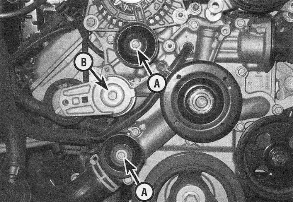
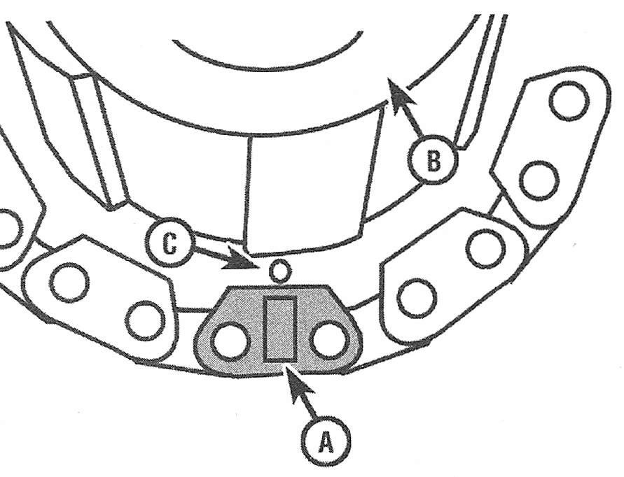
11. Remove the drivebelt tensioner and the idler pulleys (see illustration).
9.11 Idler pulley mounting bolt (A) and drivebelt tensioner mounting bolt (B) locations on the timing chain cover
12. Remove the vibration damper (Vibration damper and front oil seal – removal and installation).
13. Remove the power steering pump (see Suspension and steering systems) and set it aside without disconnecting the power steering lines.
14. Remove the dipstick tube support bolt.
15. Remove the oil pan and the pickup tube (Oil pan – removal and installation).
16. Disconnect the heater hoses from the front cover.
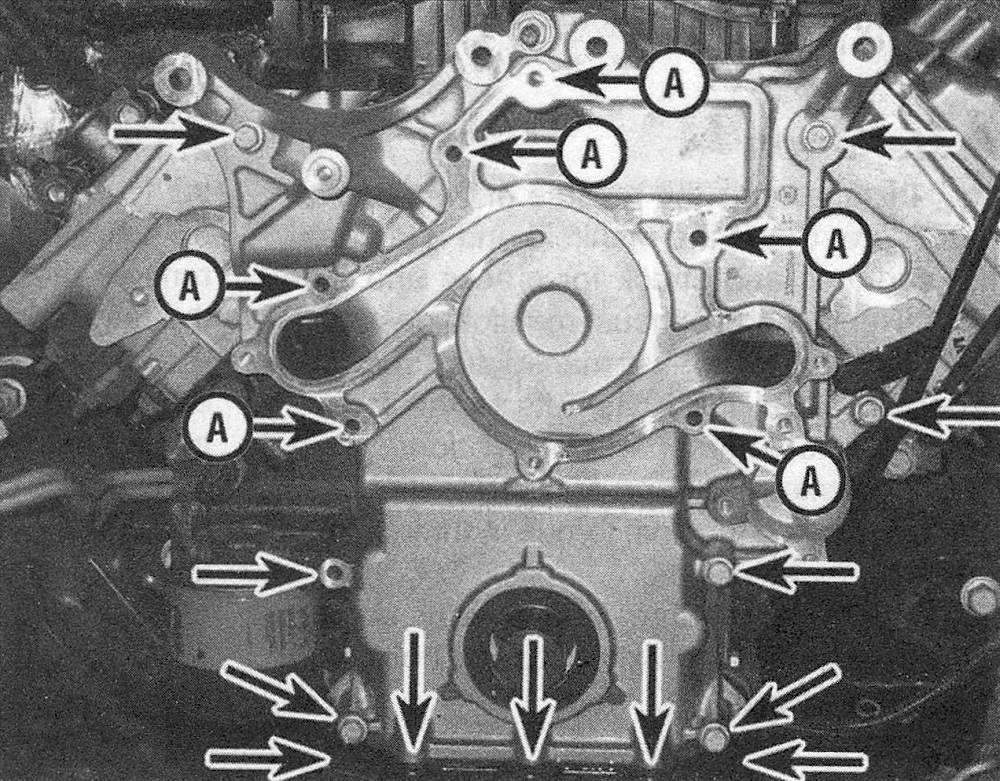
17. Remove the timing chain cover bolts (see illustration) and remove the front cover. Verify that the two upper alignment bushings remain with the cover.
9.17 Location of the timing chain cover mounting bolts – the bolt holes marked with an (A) secure the water pump as well as the timing chain cover
18. Remove the oil pump (Oil pump – removal and installation).
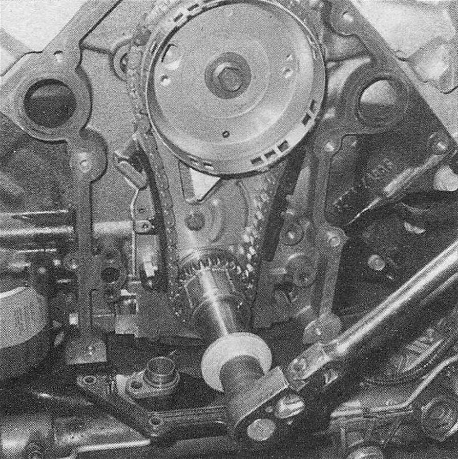
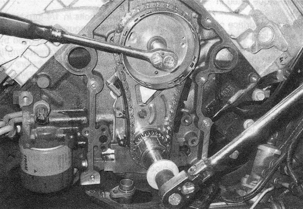
19. Reinstall the bolt into the end of the crankshaft and turn the crankshaft until the crankshaft sprocket timing mark is at the 6 o’clock position (with the crankshaft key at the 2 o’clock) and the camshaft timing mark is at the 12 o’clock position. The crankshaft sprocket mark must be aligned with the single colored link and the camshaft sprocket/phaser mark must straddle the two colored links (see illustrations).
9.19a Use a breaker bar and socket to rotate the crankshaft (clockwise) to TDC number 1 position
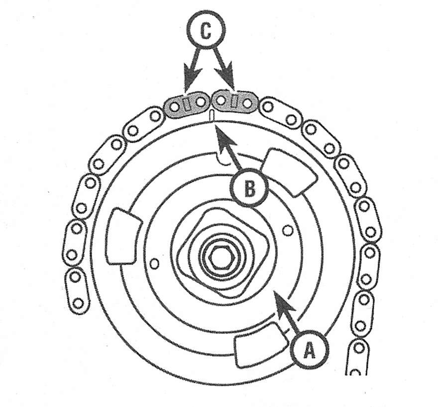
9.19b On 2009 and later models, the two colored timing chain links (C) must straddle the camshaft sprocket mark (B) on the camshaft phaser sprocket (A)
9.19c The single colored link (A) must align with the timing mark (C) on the crankshaft sprocket (B) — the keyway should be pointing to the 2 o’clock position
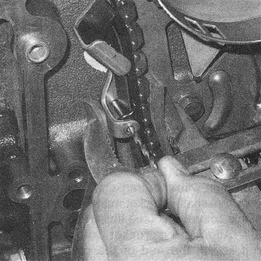
20. Retract the tensioner until the hole in the tensioner aligns with the hole in the camshaft tensioner thrust plate (see illustration). Install a suitable size drill to retain the tensioner in the retracted position.
Note: The timing chain tensioner is an integral component of the camshaft thrust plate. If necessary, the tensioner/thrust plate assembly must be replaced as a complete unit.
9.20 Use a large pair of pliers to retract the tensioner until the hole in the tensioner aligns with the hole in the bracket (thrust plate), then install a drill bit through the hole to keep it in the retracted position
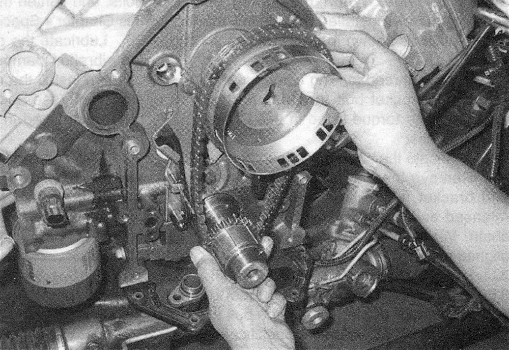
21. Remove the camshaft sprocket (phaser) bolt and remove the timing chain with the camshaft phaser and the crankshaft sprocket (see illustrations).
9.21a Use a breaker bar and socket to prevent the crankshaft from rotating while loosening the camshaft sprocket bolt
9.21b Remove the camshaft sprocket, crankshaft sprocket and timing chain as a complete assembly
Warning: Do not attempt to disassemble the camshaft phaser. It is a sealed unit and may result in extreme engine damage if it is disassembled.
22. Remove the camshaft tensioner thrust plate mounting bolts (see illustration 11.9) and separate the tensioner from the engine block.
Inspection
23. Inspect the camshaft phase for damage or wear. It should be replaced if there is any suspicion about it.
24. Inspect the crankshaft sprocket for damage or wear. The crankshaft sprocket is a steel sprocket, but these teeth can become grooved or worn enough to cause a poor meshing of the sprocket and the chain.
Installation
Caution: Before starting the engine, carefully rotate the crankshaft by hand through at least two full revolutions (use a socket and breaker bar on the crankshaft pulley center bolt). If you feel any resistance, STOP! There is something wrong – most likely, valves are contacting the pistons. You must find the problem before proceeding. Check your work and see if any updated repair information is available.
Note: Never install a new timing chain onto old sprockets.
25. Stuff a shop rag into the opening at the front of the oil pan to keep debris out of the engine, then clean off all traces of old gasket material and sealant from the engine block. Wipe the sealing surfaces with a cloth saturated with brake cleaner.
26. If the tensioner is not compressed (retracted position), compress the tensioner until the hole aligns with the bracket hole, then insert a suitable size drill bit through both holes to keep the tensioner locked in this position (see illustration 9.20). Install the camshaft thrust plate and tighten the bolts to the torque listed in this Chapter’s Specifications.
27. Assemble the timing chain, phaser and sprocket before installing them onto the engine. Loop the new chain over the camshaft phaser with the two colored links straddling the camshaft sprocket/phaser mark (see illustration 9.19b). Mesh the lower half of the chain with the crankshaft sprocket, with the crankshaft sprocket mark aligned with the single colored link (see illustration 9.19c).
28. Align the sprocket with the Woodruff key in the end of the crankshaft and assemble the chain, camshaft phaser and crankshaft sprocket onto the crankshaft and camshaft. Tap it gently into place until it is completely seated. Caution: If resistance is encountered, do not hammer the sprocket onto the crankshaft. It may eventually move onto the shaft, but it may be cracked in the process and fail later, causing extensive engine damage. When the timing chain components are installed, the timing marks MUST align as shown in illustrations 9.19b and 9.19c.
29. Apply a thread locking compound to the camshaft sprocket bolt threads and tighten the bolt to the torque listed in this Chapter’s Specifications.
30. Lubricate the chain with clean engine oil.
31. Remove the drill bit from the tensioner and bracket. Make sure the tensioner has released and is pressing against the timing chain. Verify that the timing marks are still aligned properly.
32. Install the oil pump (Oil pump – removal and installation).
33. Install the oil pump pick-up tube to the bottom of the oil pump. Tighten the bolt to the torque listed in this Chapter’s Specifications.
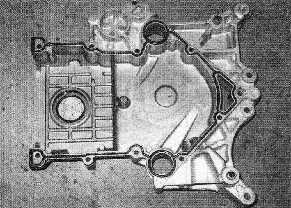
34. The timing chain cover rubber gasket can be re-used if it isn’t damaged or harderred, but considering the amount of work that you’ve done to get to this point, it’s a good idea to replace it. Double-check the surface of the timing chain cover and engine block. Make sure all old gasket material is removed and the surface is clean. Install a new rubber gasket into the groove in the timing chain cover (see illustration).
9.34 Install a new rubber gasket into the timing chain cover groove
35. Check for cracks and deformation of the oil pan gasket. If the gasket has deteriorated or is damaged, replace it (Oil pan – removal and installation).
36. Apply a small amount of RTV sealant to the corner where the timing chain cover, engine block and oil pan meet.
37. Install the timing chain cover on the block (see illustration 9.17) and tighten the bolts, a little at a time, until you reach the torque listed in this Chapter’s Specifications. Note: Install the water pump onto the timing chain cover and tighten the timing chain cover bolts and the water pump bolts at the same time (see Cooling, heating and air conditioning systems).
38. Install the oil pan-to-timing chain cover bolts, and tighten them to the torque listed in this Chapter’s Specifications.
39. Lubricate the oil seal contact surface of the vibration damper hub with clean engine oil, then install the damper on the end of the crankshaft (Vibration damper and front oil seal – removal and installation). Tighten the bolt to the torque listed in this Chapter’s Specifications.
40. The remainder of installation is the reverse of removal.
41. Add coolant and engine oil. Run the engine and check for oil and coolant leaks.