Rocker arms and pushrods – removal, inspection and installation
Removal
1. Remove the valve covers from the cylinder heads (Valve covers – removal and installation).
2. If available, install special pushrod retainer tool #9070 (or equivalent), then loosen the rocker arm shaft bolts a little at a time, starting with the center bolts and working toward the outer bolts. When the bolts have been completely loosened, lift the rocker shaft assembly off the cylinder head (see illustration). Don’t remove the retainers (under the bolt heads) from the rocker shafts.
5.2 Remove the rocker arm shaft bolts – mark each rocker arm assembly and note that the upper rocker arms are the intake and the lower rocker arms are the exhaust
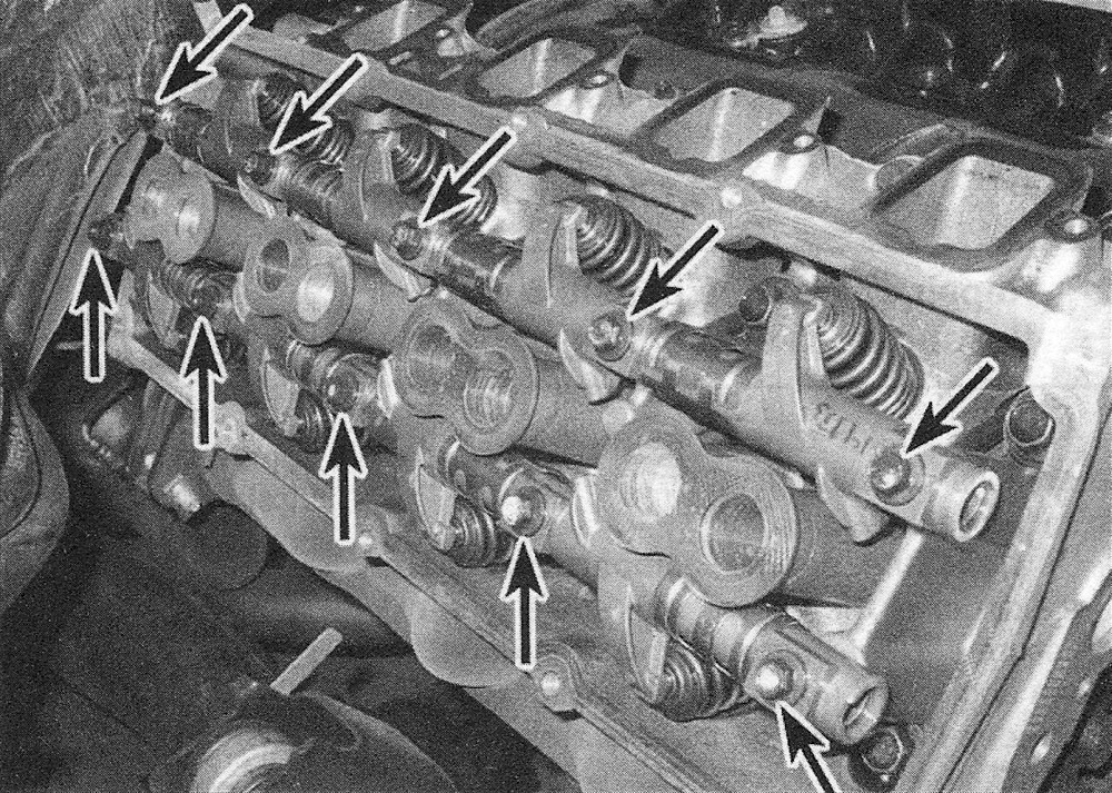
Note: If special pushrod retainer tool #9070 is not available, the rocker arm shaft bolts must be loosened no more than 1/4-turn at a time.
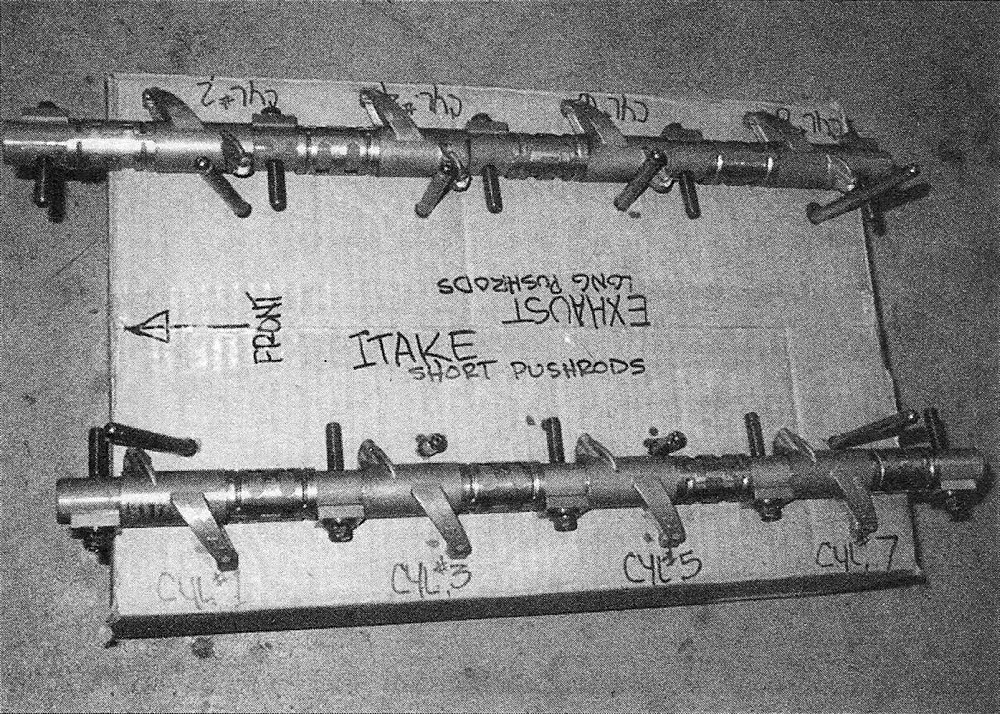
3. Keep track of the rocker arm positions, since they must be returned to the same locations. Note: The intake rockers are marked with an «I.» Store each set of rocker components in such a way as to ensure that they’re reinstalled in their original locations. Remove the pushrods and store them in order as well, to make sure they don’t get mixed up during installation (see illustration). Note: The exhaust pushrods are slightly longer than the intake pushrods – they aren’t interchangeable.
5.3 A perforated sheet of cardboard can be used to store the rocker arms and pushrods to ensure that they’re reinstalled in their original locations – note the arrow indicating the front of the engine
Inspection
Caution: If the cylinder heads have been removed and the surface milled for flatness, install correct length pushrods to compensate for the reduced distances of the rocker arms-to-camshaft dimensions. Consult with a machine shop for the correct length push-rods.
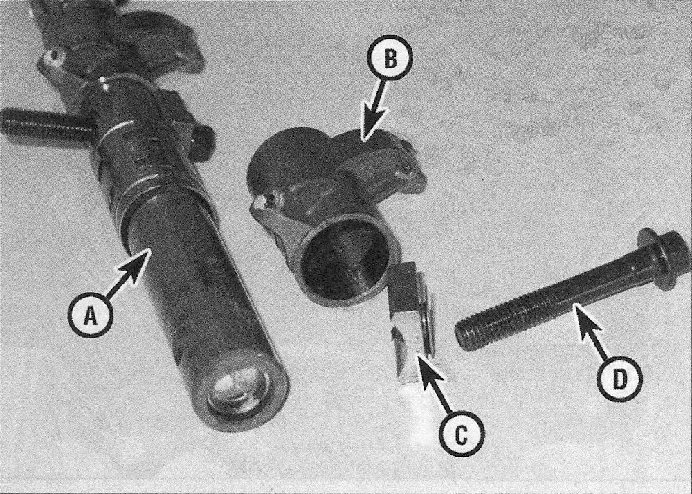
4. Check each rocker arm for wear, cracks and other damage (see illustration), especially where the pushrods and valve stems contact the rocker arm.
5.4 Rocker arm component details
A. Rocker arm shaft
B. Rocker arm
C. Retainer
D. Rocker shaft bolt
5. Check the rocker arm shafts and bores of the rocker arms for wear. Look for galling, stress cracks and unusual wear patterns. If the rocker arms are worn or damaged, replace them with new ones and install new shafts as well.
Caution: Do not remove the rocker arm retainers unless absolutely necessary. Each retainer has tangs at the bottom that can easily break off and get into the engine. If a retainer does break off, retrieve it from the rocker arm shaft prior to reassembly. Replace any retainers with broken tangs.
Note: Keep in mind that there is no valve adjustment on these engines, so excessive wear or damage in the valve train can easily result in excessive valve clearance, which in turn will cause valve noise when the engine is running.
6. Make sure the hole at the pushrod end of each rocker arm is open.
7. Inspect the pushrods for cracks and excessive wear at the ends. Roll each push-rod across a piece of plate glass to see if it’s bent (if it wobbles, it’s bent).
Installation
8. Lubricate the lower end of each pushrod with clean engine oil or engine assembly lube and install them in their original locations. Make sure each pushrod seats completely in the lifter socket.
9. Apply engine assembly lube to the ends of the valve stems and the upper ends of the pushrods to prevent damage to the mating surfaces on initial start-up.
10. Lubricate the rocker shafts with clean engine oil or engine assembly lube, then assemble the rocker shafts, with all of the components in their original positions. Install the rocker shafts onto the cylinder heads.
11. The rocker arm shafts must be tightened starting with the center bolt, then the center right bolt, the center left bolt, the outer right bolt and finally the outer left bolt. Follow this sequence in several steps until the torque listed in this Chapter’s Specifications is reached. As the bolts are tightened, make sure the pushrods seat properly in the rocker arms. Caution: Do not continue tightening the rocker arms if the rocker arm bolts become tight before the shaft is seated or the push-rods are binding. Remove the rocker arm shafts and inspect all the components carefully before proceeding.
12. Install the valve covers (Valve covers – removal and installation). Start the engine, listen for unusual valve train noses and check for oil leaks at the valve cover gaskets.