Intake manifold – removal and installation
Removal
1. Relieve the fuel system pressure (see Fuel and exhaust systems – gasoline engines). Disconnect the cable from the negative terminal of the battery (see Engine electrical systems).
2. Remove the engine cover by pulling up at the front, then sliding it forward.
3. Remove the air filter housing and the intake air duct (see Fuel and exhaust systems – gasoline engines).
4. Disconnect the brake booster vacuum hose and the PCV hose.
5. Disconnect the electrical connectors at each injector, remove the fuel rail and injectors, and disconnect all connections from the throttle body (see Fuel and exhaust systems – gasoline engines).
6. If necessary for clearance on some models, remove the air conditioning compressor without disconnecting the refrigerant lines, and set it aside (see Cooling, heating and air conditioning systems).
7. Disconnect the electrical connectors from all sensors that would interfere (see Emissions and engine control systems).
8. Remove the wiring harness support from the rear of the manifold. Also remove the air conditioning line support clip and move the line aside.
9. Remove the alternator and set it aside.
10. Remove the throttle body bracket if installed.
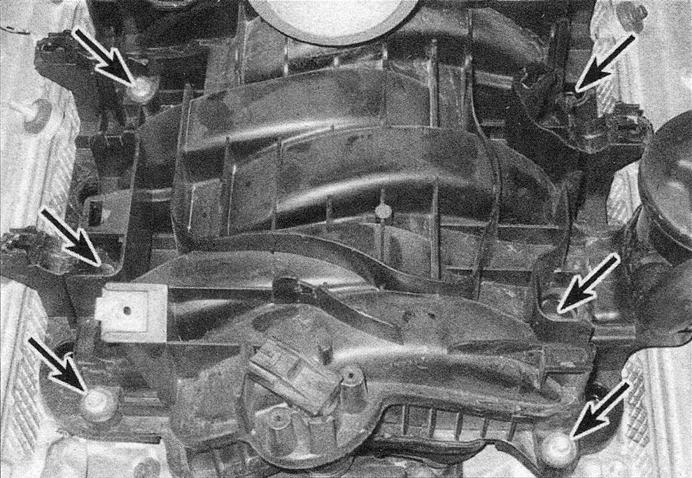
11. Loosen the intake manifold mounting bolts in 1/4-turn increments until they can be removed by hand (see illustration).
6.11 Location of the intake manifold mounting bolts – four rear mounting bolts hidden from view
Work in the same pattern as the tightening sequence (see illustration 6.16).
12. Remove the intake manifold by sliding it forward, then disconnect the MAP sensor and any other connectors.
13. As the manifold is lifted from the engine, check for and disconnect anything still attached. The throttle body can be removed now if desired.
Installation
Note: The mating surfaces of the cylinder heads and intake manifold must be perfectly clean when the manifold is installed.
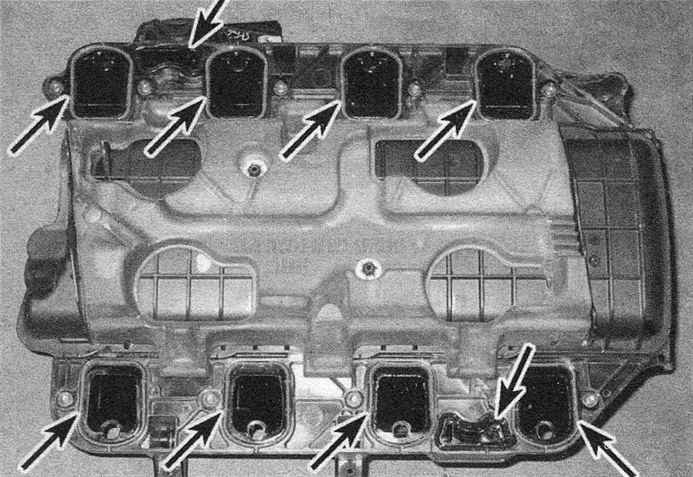
14. Check the 0-rings on the intake manifold for damage or hardening. If they’re OK, they can be re-used. If necessary, install new 0-rings (see illustration).
6.14 If necessary, replace the intake manifold 0-rings with new ones. Make sure they seat properly in their grooves
15. Carefully set the manifold in place.
Cau tion: Do not disturb the rubber seals and DO NOT move the manifold fore and aft after it contacts the cylinder heads; the seals could be pushed out of place and the engine may develop vacuum and/or oil leaks.
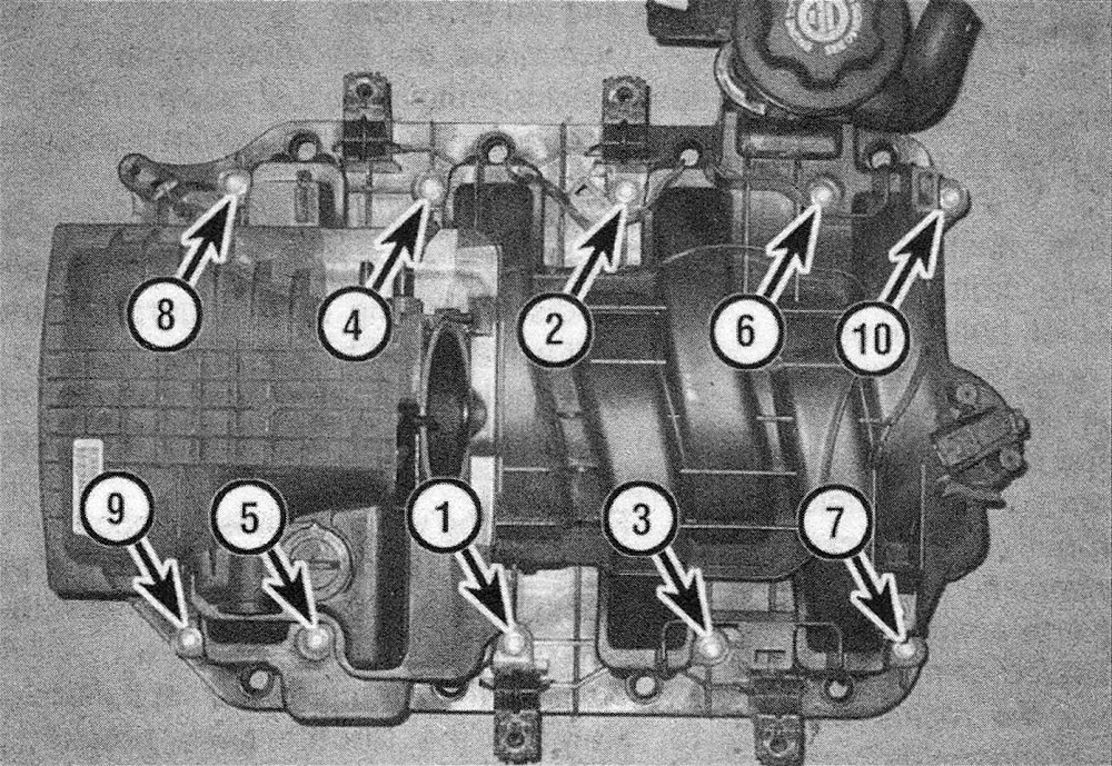
16. Install the intake manifold bolts and tighten the bolts following the correct sequence (see illustration), to the torque listed in this Chapter’s Specifications. Do not overtighten the bolts.
6.16 Tightening sequence for the intake manifold mounting bolts
17. The remainder of installation is the reverse of removal. Start the engine and check carefully for vacuum leaks at the intake manifold joints.