Camshaft and lifters – removal, inspection and installation
Warning: Wait until the engine is completely cool before beginning this procedure.
Removal
1. Relieve the fuel system pressure (see Fuel and exhaust systems – gasoline engines), then disconnect the cable from the negative terminal of the battery (see Engine electrical systems).
2. Drain the cooling system (see Tune-up and routine maintenance).
3. Remove the timing chain cover, the timing chain and the phaser (Timing chain cover, chain and sprockets – removal, inspection and installation). Remove the oil pump.
4. Remove the cylinder heads (Cylinder heads – removal and installation).
5. Remove the radiator (see Cooling, heating and air conditioning systems).
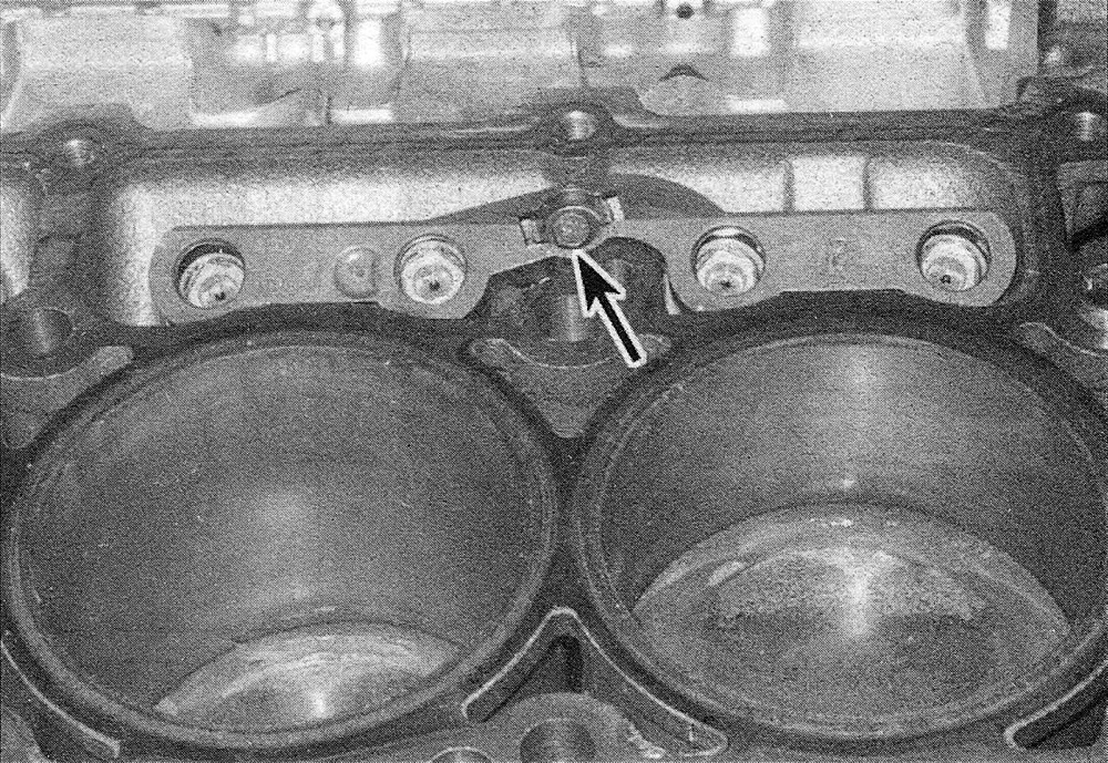
6. Remove the lifter rail mounting bolts (see illustration).
11.6 Each lifter rail is secured by one bolt
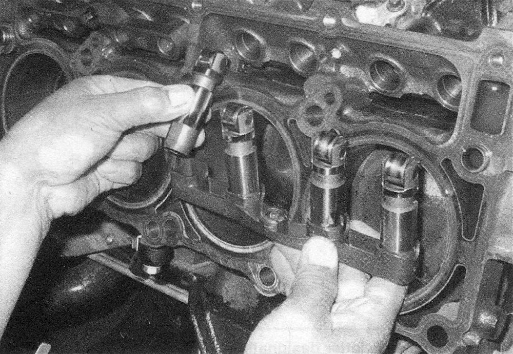
7. Remove the lifters from the lifter bores in the engine block (see illustration). On 5.7L models, carefully place them in the correct location in the lifter rail. Each lifter must be installed into the same lifter bore and in the same direction (roller rotation) (see illustration). Mark each lifter and lifter rail with a felt pen to designate the cylinder number and the type of lifter (intake or exhaust). There are several ways to extract the lifters from the bores. A special tool designed to grip and remove lifters is manufactured by many tool companies and is widely available, but it may not be required in every case. On newer engines without a lot of varnish buildup, the lifters can often be removed with a small magnet or even with your fingers. A machinist’s scribe with a bent end can be used to pull the lifters out by positioning the point under the retainer ring inside the top of each lifter.
Caution: Do not use pliers to remove the lifters unless you intend to replace them with new ones (along with the camshaft).
The pliers will damage the precision machined and hardened lifters, rendering them useless. Do not attempt to withdraw the camshaft with the lifters in place.
11.7a Remove the lifters from the lifter bores and install them into the lifter rail – each lifter must be installed into the same lifter bore and in the same direction (roller rotation)
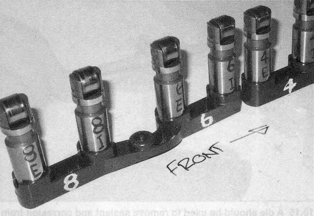
11.7b Install the lifters into the lifter rail and make sure the lifters are marked in their original position (UP) with number designations for the cylinders and letter designations for the valve each one operates (intake or exhaust)
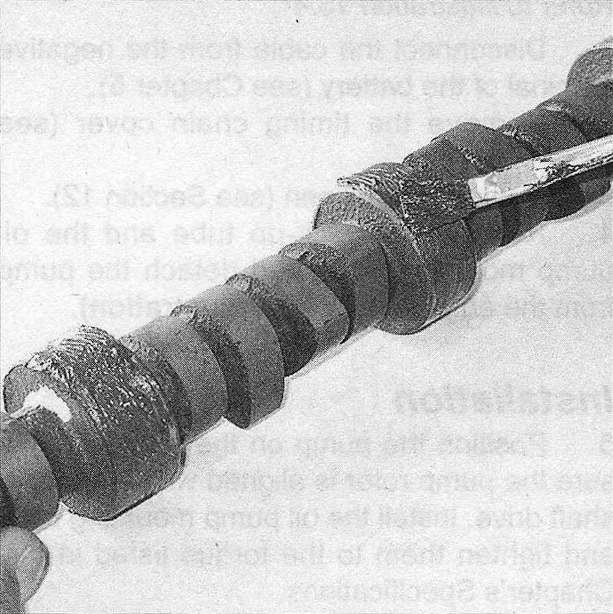
8. Before removing the camshaft, check the endplay. Mount a dial indicator so that it contacts the nose of the camshaft. Pry the camshaft forward and back using a long screwdriver with the tip taped to prevent damage to the camshaft. Record the movement of the dial indicator and compare it to this Chapter’s Specifications. If the endplay is excessive, the camshaft must be replaced.
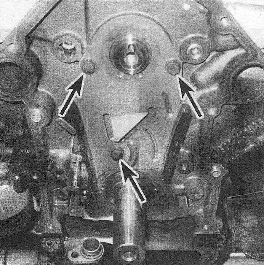
9. Unbolt and remove the camshaft thrust plate (see illustration).
11.9 Location of the camshaft thrust plate mounting bolts
10. Thread a long bolt into the camshaft sprocket bolt hole to use as a handle when removing the camshaft from the block. Carefully pull the camshaft out while slowly turning it. Support the cam near the block so the lobes do not nick or gouge the bearings as it is withdrawn.
Inspection
11. After the camshaft has been removed from the engine, cleaned with solvent and dried, inspect the bearing journals for uneven wear, pitting and evidence of seizure. If the journals are damaged, the bearing inserts in the block are probably damaged as well. Both the camshaft and bearings will have to be replaced. Note: Camshaft bearing replacement requires special tools and expertise that place it beyond the scope of the average home mechanic. The tools for bearing removal and installation are available at stores that carry automotive tools, possibly even found at a tool rental business. It is advisable though, if bearings are bad and the procedure is beyond your ability, remove the engine block and take it to an automotive machine shop to ensure that the job is done correctly.
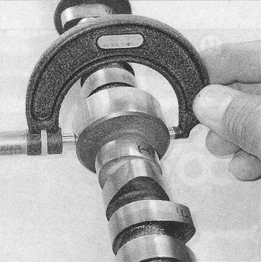
12. Measure the bearing journals with a micrometer to determine if they are excessively worn or out-of-round (see illustration).
11.12 Check the diameter of each camshaft bearing journal to pinpoint excessive wear and out-of-round conditions
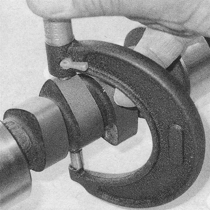
13. Measure the lobe height of each cam lobe on the intake camshaft and record your measurements (see illustration). Compare the measurements for excessive variations. If the lobe heights vary more than 0.005 inch (0.125 mm), replace the camshaft. Compare the lobe height measurements on the exhaust camshaft and follow the same procedure. Do not compare intake camshaft lobe heights with exhaust camshaft lobe heights, as they are different. Only compare intake lobes with intake lobes and exhaust lobes with other exhaust lobes.
11.13 Measure the camshaft lobe height (greatest dimension) with a micrometer
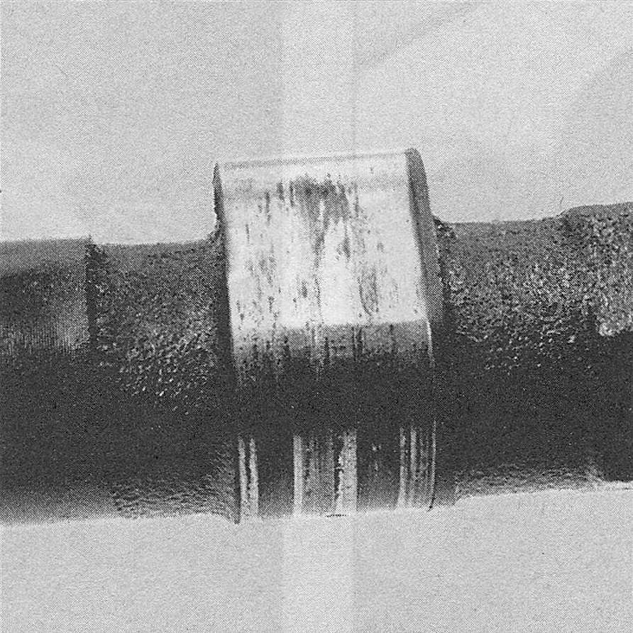
14. Check the camshaft lobes for heat discoloration, score marks, chipped areas, pitting and uneven wear (see illustration). If the lobes are in good condition and if the lobe lift variation measurements recorded earlier are within the limits, the camshaft can be reused.
11.14 Check the cam lobes for pitting, excessive wear and scoring. If scoring is excessive, as shown here, replace the camshaft
15. Clean the lifters with solvent and dry them thoroughly without mixing them up.
16. Check each lifter wall, pushrod seat and foot for scuffing, score marks and uneven wear. If the lifter walls are damaged or worn (which is not very likely), inspect the lifter bores in the engine block as well. If the push-rod seats are worn, check the pushrod ends.
17. If new lifters are being installed, a new camshaft must also be installed. If a new camshaft is installed, then use new lifters as well. Never install used lifters unless the original camshaft is used and the lifters can be installed in their original locations.
18. Check the rollers carefully for wear and damage and make sure they turn freely without excessive play (see illustration).
11.18 The roller on the roller lifters must turn freely – check for wear and excessive play as well
Installation
19. Lubricate the camshaft bearing journals and cam lobes with camshaft installation lube (see illustration).
11.19 Apply camshaft installation lube to the cam lobes and bearing journals before installing the camshaft
20. Slide the camshaft slowly and gently into the engine. Support the cam near the block and be careful not to scrape or nick the bearings. Only install the camshaft far enough to install the camshaft thrust plate. Pushing it in too far could dislodge the camshaft plug at the rear of the engine, causing an oil leak. Tighten the camshaft thrust plate mounting bolts to the torque listed in this Chapter’s Specifications.
21. Install the timing chain and sprockets (Timing chain cover, chain and sprockets – removal, inspection and installation). Align the timing marks on the crankshaft and camshaft sprockets.
22. Lubricate the lifters with clean engine oil and install them in the block. If the original lifters are being reinstalled, return them to their original locations, and with the numbers facing UP (exactly as they were removed). Install the lifter rail and mounting bolts. Tighten the lifter rail mounting bolts to the torque listed in this Chapter’s Specifications. Note: Each lifter rail should be numbered and coincide with the correct cylinder numbers.
23. The remainder of, installation is the reverse of removal.
24. Change the oil and install a new oil filter (see Tune-up and routine maintenance). Fill the cooling system with the proper type of coolant (see Tune-up and routine maintenance).
25. Start the engine and check for oil pressure and leaks.
Caution: Do not run the engine above a fast idle until all the hydraulic lifters have filled with oil and become quiet again
26. If a new camshaft and lifters have been installed, the engine should be brought to operating temperature and run at a fast idle for 15 to 20 minutes to break in the new components. Change the oil and filter again after 500 miles of operation.