Intake manifold, air heater and air heater relay – replacement
Intake manifold
2009 models
Note: The two intake air heater elements are housed inside a metal block that’s bolted to the top of the intake manifold cover by the four intake air heater manifold bolts. The metal block and intake air heater elements are not serviceable separately. They must be replaced as a single assembly.
1. Disconnect the cables from both negative battery terminals (see Engine electrical systems).
2. Disconnect the wiring from the EGR temperature sensor and the EGR valve actuator.
3. Remove the fasteners from the oil dipstick tube.
4. Remove the intercooler outlet tube.
5. Remove the air transfer tube and the bolt from the P-clip.
6. Remove the six air inlet bolts and the air inlet.
7. Carefully clean each end of each fuel supply tube, then remove the lines that are accessible. You’ll have to loosen and tilt the bracket on the rear of the cylinder head for access to the rear fuel line fittings.
8. Disconnect the wiring from the sensor at the rear of the fuel rail.
9. Remove the high pressure fuel line from the dump valve.
10. Remove the fuel rail.
11. Disconnect the remaining wiring harnesses from the intake manifold.
12. Remove the intake manifold.
13. Remove the front fuel inlet lines that are now accessible, if necessary.
14. Installation is the reverse of removal.
2010 and later models
15. Disconnect the cables from both negative battery terminals (see Engine electrical systems).
16. Disconnect the left intercooler tube from the EGR air flow control valve.
17. Remove the EGR crossover tube.
18. Disconnect the interfering wiring harnesses.
19. Remove the bolt and the nut from the oil dipstick tube.
20. Remove the bolts and the intake manifold. Discard the gasket; it must be replaced with a new one.
21. Installation is the reverse of removal.
Air heater
22. The two intake air heater grids are housed inside a metal box, which is located on top of the intake manifold cover. The intake air heater elements heat incoming air to make the engine easier to start during cold start-ups and to improve drivability in cool and cold ambient temperatures. The Engine Control Module (ECM) controls the current to the heater elements through two heater relays located in the engine compartment.
23. Remove the intake manifold (see earlier in this Section).
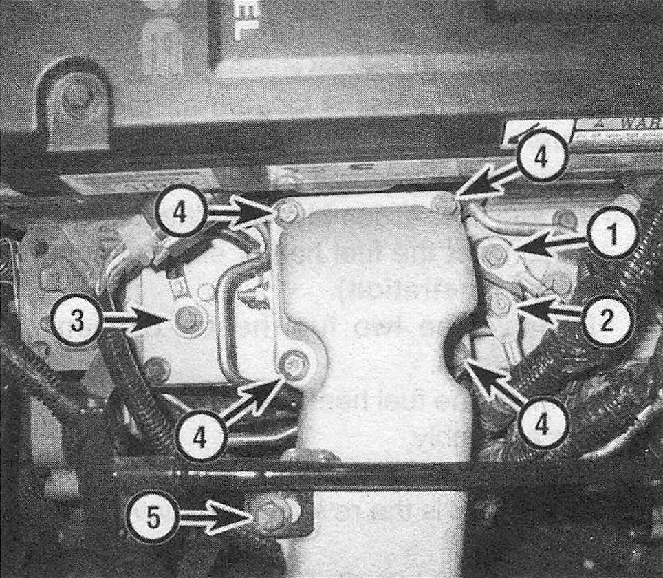
24. Disconnect the heater cable from the heater (see illustrations). Also disconnect and remove the fuel injector wiring harness. Disconnect the pressure sensor wiring harness from the valve cover.
9.24a To access the intake air heater elements, disconnect or remove the following:
1. Heater grid positive cable nut
2. Heater grid positive cable nut
3. Heater grid ground cable – it’s not necessary to remove this bolt unless you’re replacing the ground cable; instead disconnect the other end of the ground cable from its terminal stud
4. Intake air heater manifold bolts
5. Dipstick tube mounting bracket bolt
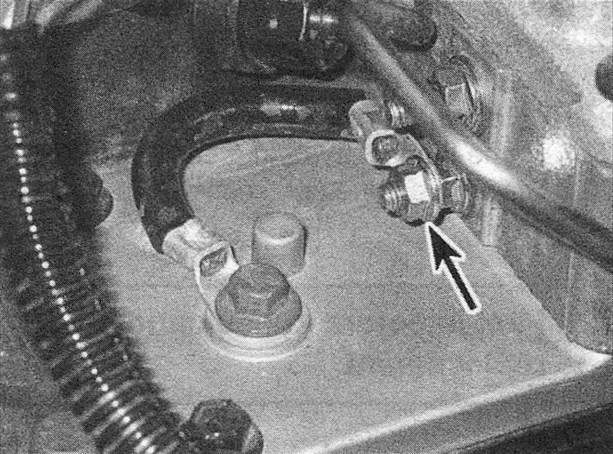
9.24b To disconnect the heater element ground strap from its stud terminal, remove this nut
25. Detach the vent tube from the valve cover, then remove the air intake heater mounting bolts. Lift the heater assembly off and discard its gasket.
26. Installation is the reverse of removal. Clean the old gasket material from the air intake housing and intake manifold and from both ends of the heater block.
27. Use new upper and lower heater block gaskets and tighten the air intake housing bolts to the torque listed in this Chapter’s Specifications.
Air heater relay
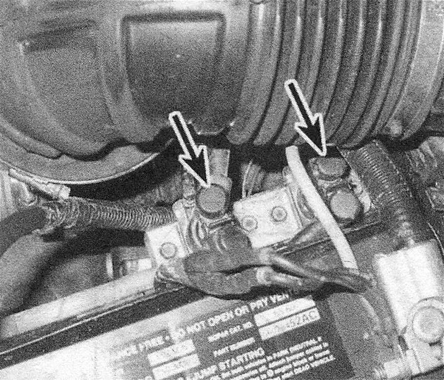
28. The intake air heater relay is located in the engine compartment on a bracket that is bolted to the right battery tray (see illustration). The following replacement procedure applies to all heater relays.
9.28 The two heater relays are located next to the right battery
29. Disconnect the cables from both negative battery terminals.
30. Clearly label the trigger wires, then disconnect them.
31. Remove the nuts from the cable terminals and disconnect the cables. Label the wires to prevent crossed wires during reassembly.
32. Remove the relay mounting bracket bolts and remove the relay.
33. Installation is the reverse of removal.