Fuel injection pump – removal and installation
Removal
1. Disconnect the cables from the negative battery terminals (see Engine electrical systems).
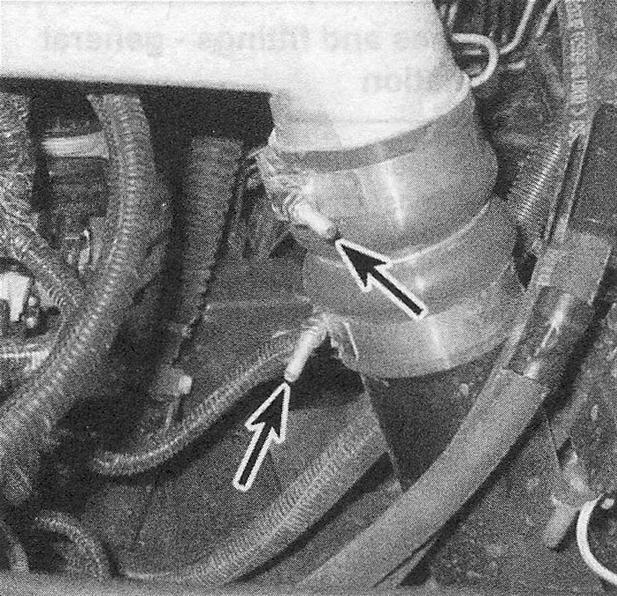
2. Remove the air inlet tube and its hose from above the injection pump (see illustration).
6.2 Loosen the hose clamps on the connecting tubes for the intercooler duct at each end of the duct, then remove the duct
3. Remove the drivebelt (see Tune-up and routine maintenance).
4. Clean the rear part of the injection pump and the line fittings. Clean the other ends of the line fittings to avoid contamination when they’re disassembled.
5. Detach the fuel line quick-connect fitting by pushing its button.
6. Remove the high pressure fuel line that attaches to the fuel rail.
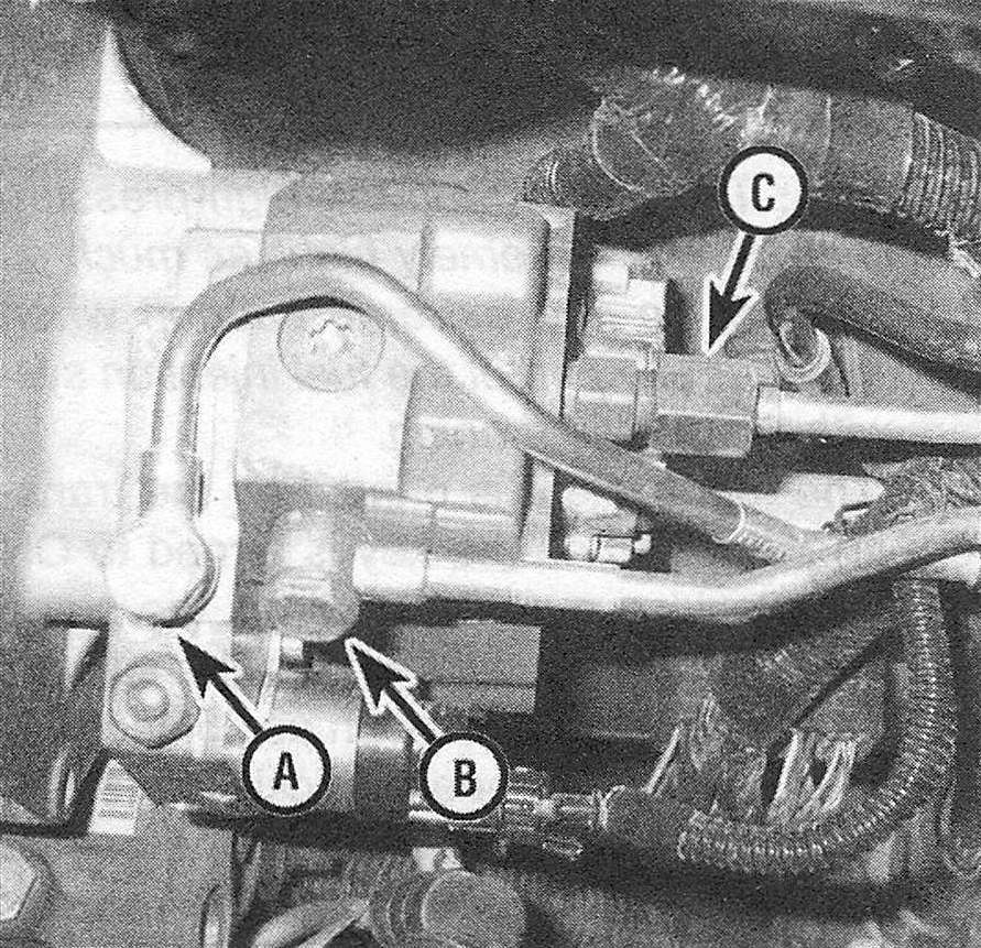
7. Remove the banjo bolt from directly above the quick-connect fitting (see illustration). Remove the old sealing washers from the banjo bolts and discard them. Always use new sealing washers when reconnecting these banjo fittings.
6.7 Fuel injection pump-to-fuel line fittings
A. Banjo bolt for fuel filter/water separator-to-injection pump line
B. Banjo bolt for fuel pressure limiting valve (on fuel rail)-to-injection pump line
C. Tube nut type fitting for high-pressure line to fuel rail
8. Disconnect the wiring from the fuel control actuator on the rear of the pump, then remove the clamp that secures the two fuel lines to each other.
9. Unscrew the fuel pump access cover using a ratchet with no socket on it.
10. Remove the nut and the washer from the fuel pump drive gear.
11. Attach a suitable gear puller to the pump drive gear with two bolts and separate the gear from the pump. Leave it in the housing for now.
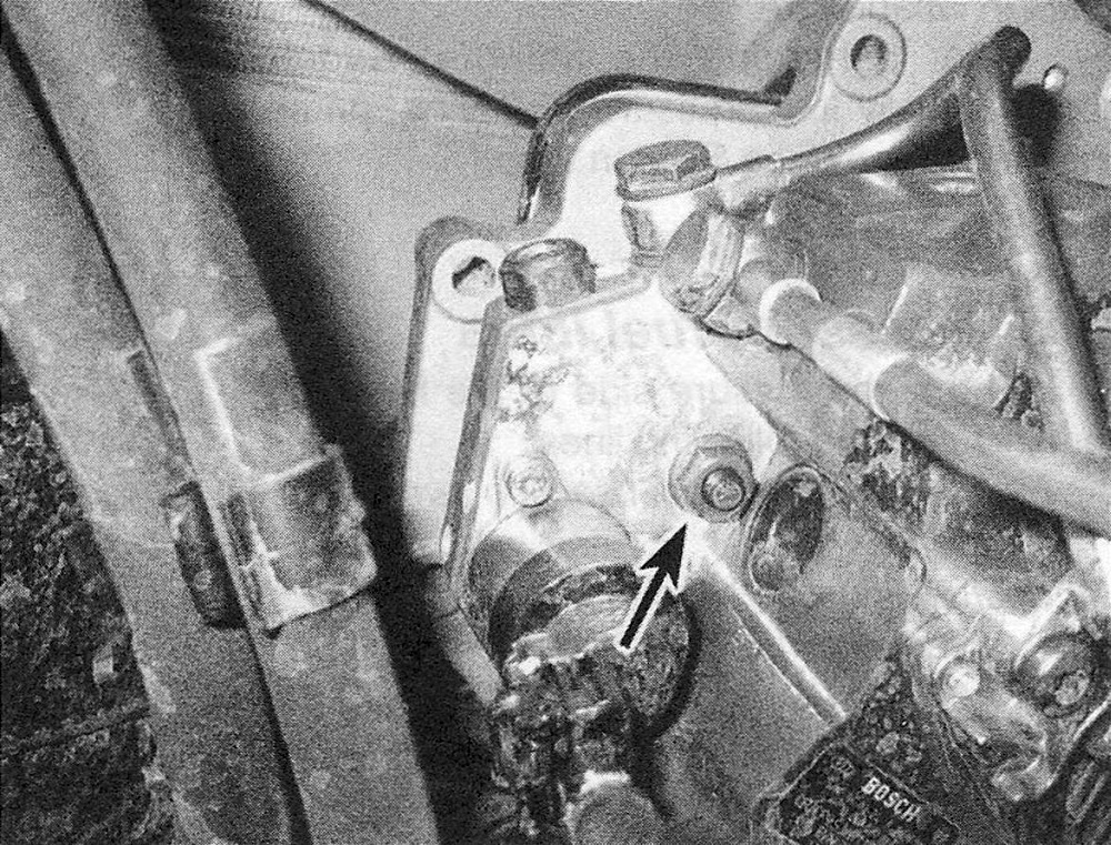
12. Remove the three injection pump mounting nuts (see illustration) and remove the pump from the engine.
6.12 To detach the fuel injection pump from the timing gear cover, remove the three pump mounting nuts (other two nuts not shown)
13. Remove the old injection pump 0-ring from the machined groove in the pump mounting surface. Discard the 0-ring.
Installation
14. Thoroughly clean off the pump mounting surfaces of the pump and the timing gear cover. Also clean off the machined tapers on both the injection pump shaft and on the injection pump gear using lacquer thinner or acetone. These surfaces must be absolutely dry and free of all dirt and oil to ensure correct gear-to-shaft mounting.
15. Apply a little clean engine oil to the new injection pump 0-ring, then install a new 0-ring into the machined groove in the pump mounting surface.
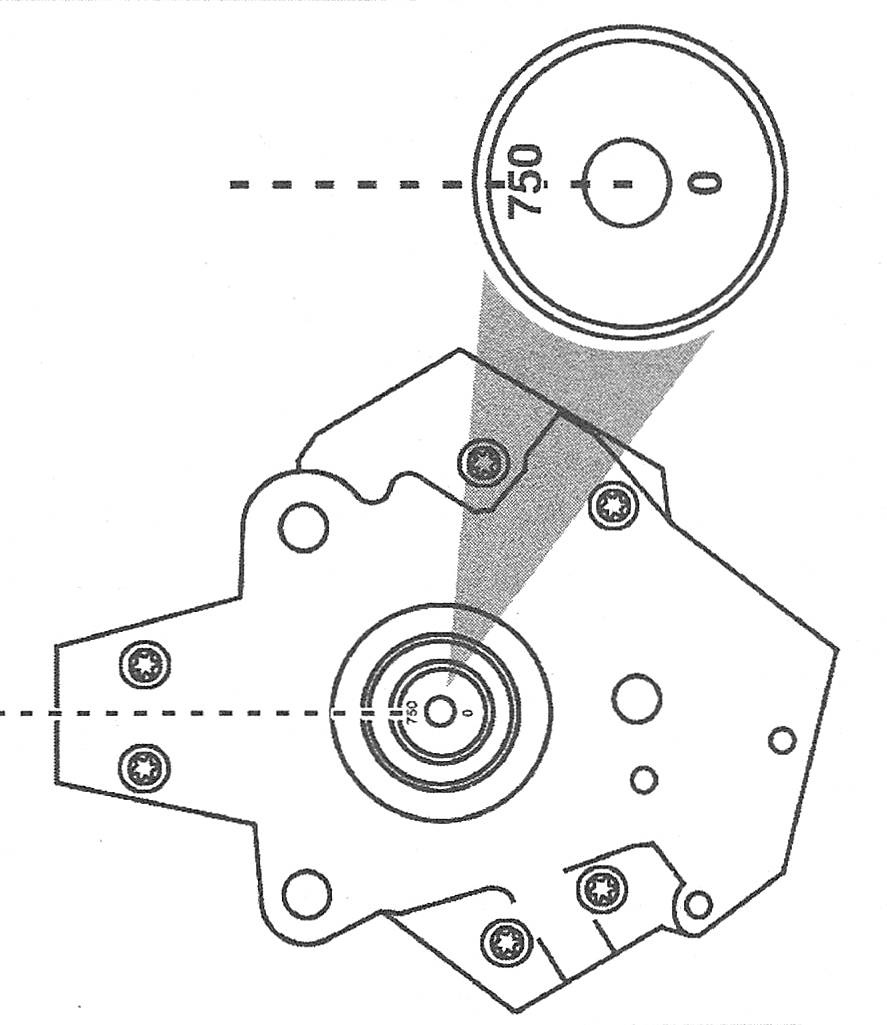
16. Check the fuel injection pump phasing before installing the pump onto the engine. Locate the numbers on the fuel injection pump shaft. There should be a 0 and 750 or a 754 stamped into the shaft. Set the number «5″ digit at the 9 o’clock position (see illustration). Place the pump in position on the rear of the timing gear cover with the digit «5″ set in the 9 o’clock position. Make sure the engine is at TDC (see Chapter Diesel engine).
Note: The engine can be positioned in TDC number 1 or TDC number 6 for this procedure.
6.16 Set the fuel injection pump phasing with the digit «5″ in the 9 o’clock position
17. Once the pump is flush with the mounting surface on the timing gear cover, install the three pump mounting nuts and tighten them finger tight. To prevent damage to any components, tighten the injection pump mounting nuts and the drive gear-to-pump shaft nut in the following sequence:
a) Install the washer and nut on the injection pump shaft and hand tighten the nut until it’s finger tight, then carefully tighten it a bit more.
b) Tighten the three injection pump mounting nuts to the torque listed in this Chapter’s Specifications.
c) Tighten the injection pump shaft-to-gear nut to the torque listed in this Chapter’s Specifications.
18. Using new sealing washers, reconnect the fuel line banjo bolts and tighten them to the torque listed in this Chapter’s Specifications. Reconnect the tube nut fitting for the high-pressure fuel line and tighten it to the torque listed in this Chapter’s Specifications.
19. The remainder of installation is the reverse of removal.
20. Reconnect the cables to the negative battery terminals.
21. Prime the fuel system (Fuel system priming).
22. Start the engine and check for fuel leaks.