Battery – check and replacement
Warning: Hydrogen gas is produced by the battery, so keep open flames and lighted cigarettes away from it at all times. Always wear eye protection when working around a battery. Rinse off spilled electrolyte immediately with large amounts of water.
Caution: Always disconnect the negative cable first and hook it up last or you might accidentally short the battery with the tool that you’re using to loosen the cable clamps.
Check
1. To check the battery state of charge, look at the indicator eye on the top of the battery (the eye is the top of a hydrometer that’s built into the battery). If the indicator eye is green, the battery is 75 to 100 percent charged. If the indicator eye is black, the battery is 0 to 75 percent charged. If the indicator eye is clear (or bright), the battery electrolyte level is low. All factory-installed batteries are the maintenance-free type; the cell caps cannot be removed, so no water can be added. If the indicator eye is clear on a maintenance-free battery, replace the battery. If the maintenance-free battery has been replaced by a low-maintenance battery with removable cell caps, remove the caps and add enough water to bring it up to the correct level (which should be marked on the outside of the battery case). If there are no MINIMUM and MAXIMUM lines on the battery case, add enough water to each cell so that the plates are fully immersed. Wait a few hours for the electrolyte in the plates to go back into solution, then charge the battery (see Tune-up and routine maintenance).
Note: A low-electrolyte/lowwater condition is often a symptom of overcharging, so after recharging the battery, check the alternator charging voltage (Charging system – check) and, if necessary, replace the alternator. Otherwise, the same condition will reoccur.
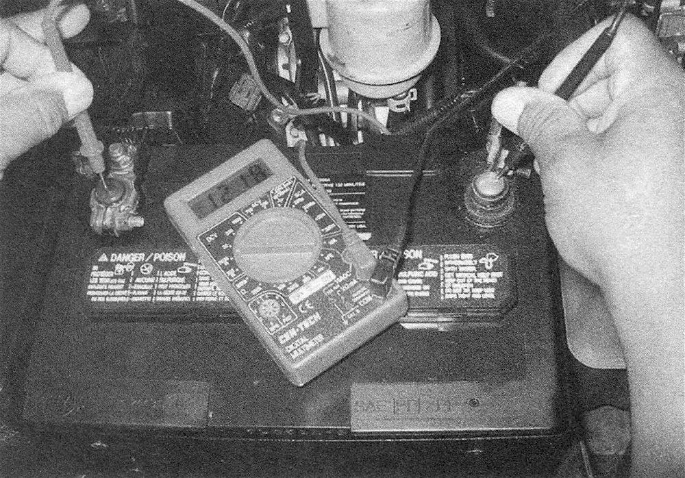
2. Perform an open-voltage circuit test using a voltmeter (see illustration).
Note: To obtain an accurate voltage measurement, you must first remove the battery’s surface charge. To remove the surface charge, turn on the high beams for ten seconds, then turn them off and let the vehicle stand for two minutes. With the engine and all accessories off, touch the negative probe of the voltmeter to the negative terminal of the battery and the positive probe to the positive terminal of the battery. The battery voltage should be 12.6 volts or more. If the battery is less than the specified voltage, charge the battery before proceeding to the next test. Do not proceed with the battery load test unless the battery charge is correct.
3.2 To test the open circuit voltage of the battery, connect a voltmeter to the battery terminals. A fully charged battery should have at least 12.6 volts
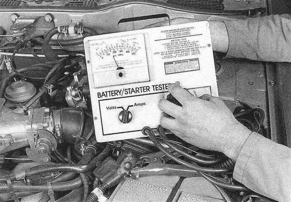
3. Perform a battery load test. An accurate check of the battery condition can only be performed with a battery load tester (available at most auto parts stores). This test evaluates the ability of the battery to operate the starter and other accessories during periods of heavy amperage draw (load). The tool utilizes a carbon pile to increase the load demand (amperage draw) on the battery. Install a special battery load-testing tool onto the terminals (see illustration). Load test the battery according to the tool manufacturer’s instructions. Typically a load of 50-percent of the cold cranking amperage rating is applied during the test. The cold cranking amperage rating can usually be found on the battery label. Maintain the load on the battery for a maximum of 15 seconds. The battery voltage should not drop below 9.6 volts during the test. If the battery condition is weak or defective, the tool will indicate this condition immediately.
Note: Cold temperatures will cause the voltage readings to drop slightly. Follow the chart given in the tool manufacturer’s instructions to compensate for cold climates. Minimum load voltage for freezing temperatures (32-degrees F) should be approximately 9.1 volts.
3.3 Connect a battery load tester to the battery and check the battery condition under load following the tool manufacturer’s instructions
Replacement Battery
4. Disconnect the cable from the negative battery terminal (see illustration), then disconnect the cable from the positive terminal.
3.4 When disconnecting the battery cables, always disconnect the cable from the negative terminal (1) first, then disconnect the cable from the positive terminal (2). After the battery cables are disconnected, remove the battery hold-down bolt (3) and the hold down clamp (4)
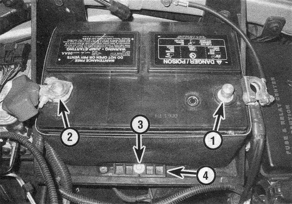
5. Remove the battery hold-down bolt and hold-down clamp.
6. Lift out the battery. Be careful – it’s heavy.
Note: Battery straps and handlers are available at most auto parts stores for a reasonable price. They make it easier to remove and carry the battery
7. While the battery is out, inspect the area underneath the tray for corrosion. Clean the battery tray, then use a baking soda/water solution to neutralize any deposits to prevent further oxidation. If the metal around the tray is corroded, too, clean it as well and spray the area with a rust-inhibiting paint.
8. If corrosion has leaked down past the battery tray, remove the tray (see Steps 12 through 23) for further cleaning.
9. If you are replacing the battery, make sure you get one that’s identical, with the same dimensions, amperage rating, cold cranking rating, etc.
10. Installation is the reverse of removal.
Battery tray Left side
11. Remove the battery (see Steps 4 through 6).
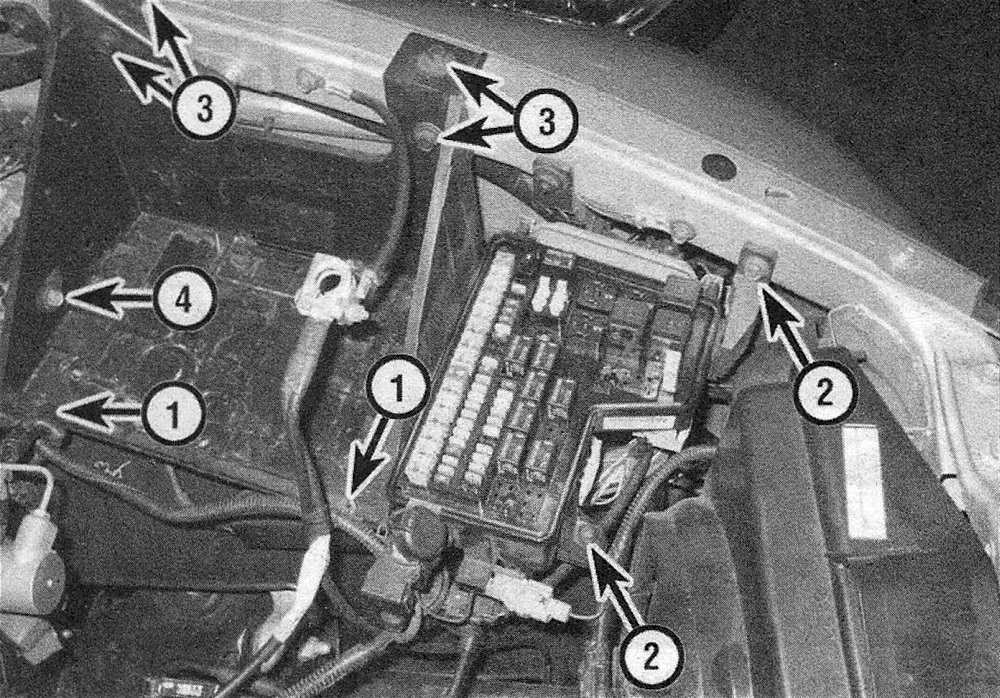
12. Detach the wiring harness clips from the battery tray (see illustration).
3.12 Top battery tray mounting details
1 Wiring harness clips
2. Fuse/relay box mounting fasteners
3. Tray mounting bolts
4. ABS controller bolt
13. Remove the engine compartment fuse and relay box mounting bolts.
14. Slide the fuse and relay box towards the center of the engine compartment to disengage the two locator pins from their respective slots in the front wall of the battery box and lift up the fuse and relay box.
15. Remove the ABS controller mounting bolt, then support the controller with some wire or with a bungee cord.
16. Loosen the lug nuts for the left front wheel. Raise the front of the vehicle and place it securely on jackstands. Remove the left front wheel. Remove the left front wheelhouse splash shield (see Body).
17. Mark the location of the cruise control servo (if equipped), then remove the servo retaining screws and detach the servo from the battery tray.
18. Unplug the electrical connector from the battery temperature sensor if your vehicle uses one.
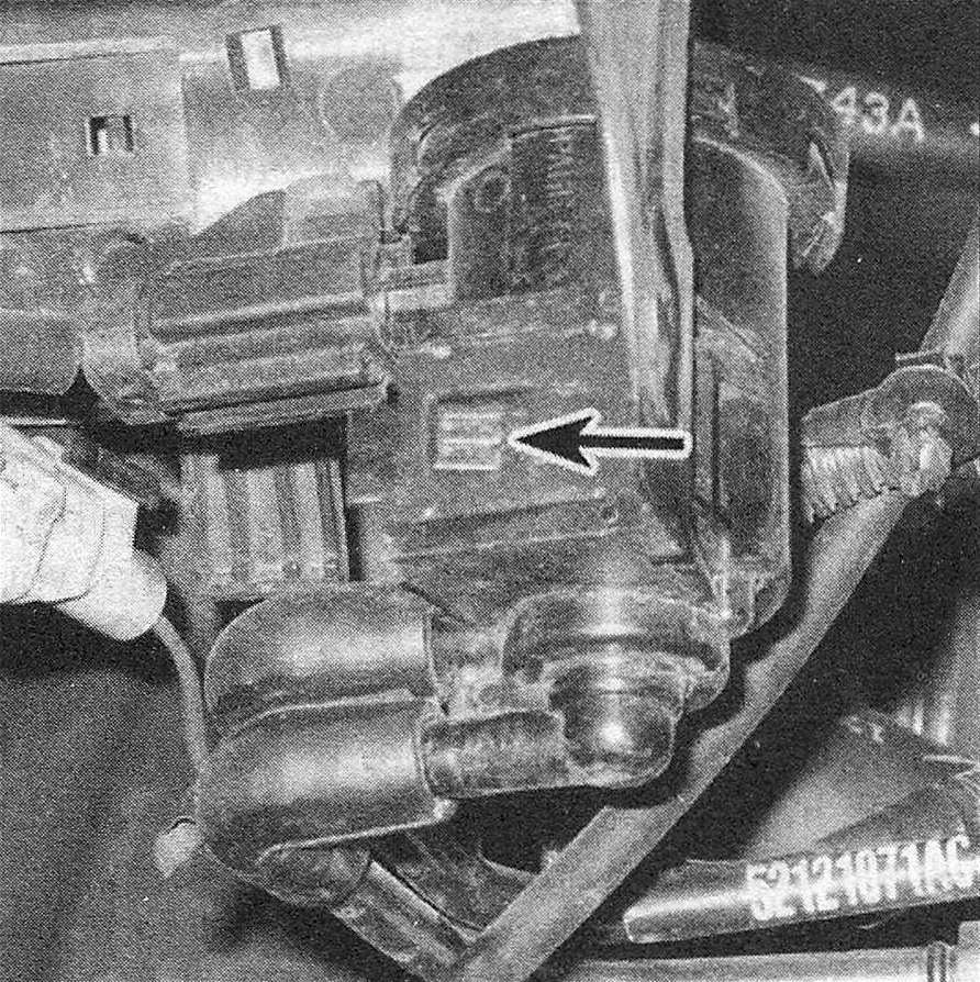
19. Detach the Evaporative Emissions (EVAP) system purge solenoid from its mounting bracket (see illustration). It’s not necessary to disconnect the electrical connector from the purge solenoid or to detach the solenoid mounting bracket from the battery tray, which is attached to the underside of the tray by a pair of retaining screws (unless you’re planning to replace the tray).
3.19 To detach the EVAP purge solenoid from its mounting bracket, depress this locking tang and slide the solenoid off its bracket
20. Disconnect the ground cable from the left front fender (on most models).
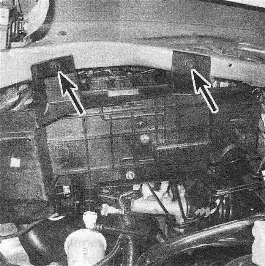
21. Remove the battery tray mounting bolts and remove the battery tray (see illustration).
3.21 Battery tray lower details and mounting bolts
22. Installation is the reverse of removal.
Right side
23. Removal of the right-side battery tray, on models so equipped, is similar to the removal procedure of the left side battery tray, except that the air filter housing and the relay bracket must be removed (see Chapter Fuel and exhaust systems – gasoline engines ; Fuel and exhaust systems – diesel engine), and some of the steps related to left side tray removal will not apply.