Oxygen sensors – general description and replacement
General description
1. The oxygen in the exhaust reacts with the elements inside the oxygen sensor to produce a voltage output that varies from 0.1 volt (high oxygen, lean mixture) to 0.9 volt (low oxygen, rich mixture). The pre-converter oxygen sensor (mounted in the exhaust system before the catalytic converter) provides a feedback signal to the PCM that indicates the amount of leftover oxygen in the exhaust. The PCM monitors this variable voltage continuously to determine the required fuel injector pulse width and to control the engine air/fuel ratio. Based on oxygen sensor signals, the PCM tries to maintain the ideal air/fuel ratio at all times.
2. The post-converter oxygen sensor (mounted in the exhaust system after the catalytic converter) has no effect on PCM control of the air/fuel ratio. However, the post-converter sensor is identical to the pre-converter sensor and operates in the same way. The PCM uses the post-converter signal to monitor the efficiency of the catalytic converter. A post-converter oxygen sensor will produce a slower fluctuating voltage signal that reflects the lower oxygen content in the post-catalyst exhaust.
3. Oxygen sensor configuration varies depending on the model and on where it is sold; Federal (49-State) model or California model.
4. An oxygen sensor produces no voltage when it is below its normal operating temperature of about 600-degrees F. During this warm-up period, the PCM operates in an open-loop fuel control mode. It does not use the oxygen sensor signal as a feedback indication of residual oxygen in the exhaust. Instead, the PCM controls fuel metering based on the inputs of other sensors and its own programs.
5. An oxygen sensor depends on four conditions in order to operate correctly:
a) Electrical – The low voltage generated by the sensor requires good, clean connections. Always check the connectors whenever an oxygen sensor problem is suspected or indicated.
b) Outside air supply – The sensor needs air circulation to the internal portion of the sensor. Whenever the sensor is installed, make sure that the air passages are not restricted.
c) Correct operating temperature – The PCM will not react to the sensor signal until the sensor reaches approximately 600-degrees F. This factor must be considered when evaluating the performance of the sensor.
d) Unleaded fuel – Unleaded fuel is essential for correct sensor operation.
6. The PCM can detect several different oxygen sensor problems and set Diagnostic Trouble Codes (DTCs) to indicate the specific fault (On-Board Diagnostic (OBD) system and Diagnostic Trouble Codes (DTCs)). When an oxygen sensor DTC occurs, the PCM disregards the oxygen sensor signal voltage and reverts to open-loop fuel control as described previously.
Replacement
Warning: Be careful not to burn yourself during the following procedure.
Note: Since the exhaust pipe contracts when cool, the oxygen sensor may be hard to loosen. To make sensor removal easier, start the engine and let it run for a minute or two, then turn it off.
7. Raise the vehicle and place it securely on jackstands.
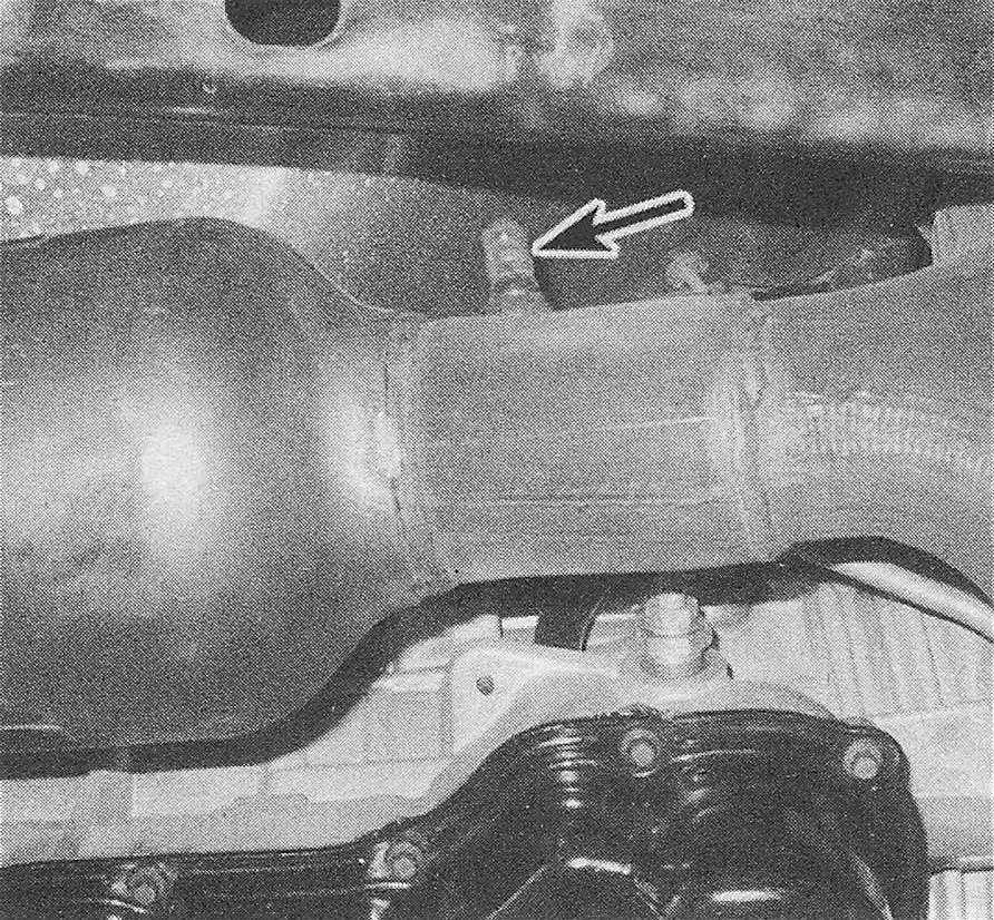
8. Locate the upstream or downstream oxygen sensor (see illustrations), trace the sensor’s electrical lead to the sensor electrical connector and disconnect it.
11.8a The upstream oxygen sensor is located ahead of the catalytic converter. To find the electrical connector, trace the electrical lead from the sensor to the connector and disconnect it (Hemi shown, others similar)
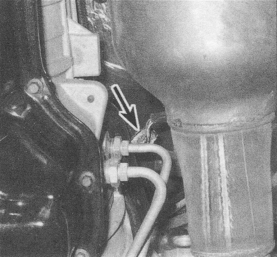
11.8b The downstream oxygen sensor (not visible in this photo, but shown in the next photo) is located behind the catalyst. First, disconnect the electrical connector, then trace the lead up to the sensor
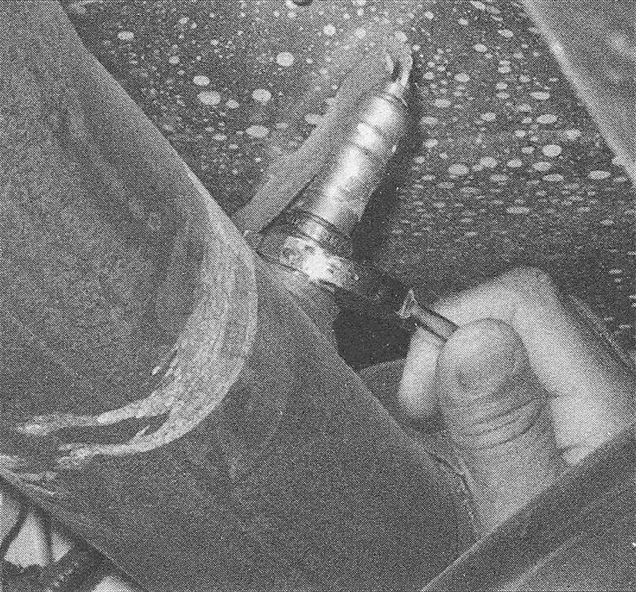
9. Remove the upstream or downstream oxygen sensor. On some models you can remove the sensor with a wrench (see illus tration). On others, you will have to use an oxygen sensor socket (available at most auto parts stores).
11.9 Remove an oxygen sensor with a wrench if you can (this is the downstream sensor). If there’s not enough room for a wrench you might have to use an oxygen sensor socket (available at most auto parts stores)
10. Clean the threads inside the sensor mounting hole in the exhaust pipe with an appropriate tap.
11. If you’re installing the old sensor, clean off the threads, then apply a coat of anti-seize compound to the threads before installing the sensor. If you’re installing a new sensor, do NOT apply anti-seize compound; new sensors are already coated with anti-seize.
12. Installation is otherwise the reverse of removal. Tighten the oxygen sensor to the torque listed in this Chapter’s Specifications.