On-Board Diagnostic (OBD) system and Diagnostic Trouble Codes (DTCs)
Scan tool information
1. Hand-held scanners are handy for analyzing the engine management systems used on late-model vehicles. Because extracting the Diagnostic Trouble Codes (DTCs) from an engine management system is now the first step in troubleshooting many computer-controlled systems and components, even the most basic generic scan tools are capable of accessing a computer’s DTCs. More powerful scan tools can also perform many of the diagnostics once associated with expensive factory scan tools. If you’re planning to obtain a generic scan tool for your vehicle, make sure that it’s compatible with the year, make and model of the vehicle(s) on which you plan to use it. Some of the more versatile scan tools accept removable cartridges, each of which contains the diagnostics for a particular manufacturer. An aftermarket generic scanner should work with any model covered by this manual. But before purchasing a scan tool, contact the manufacturer of the scanner you’re planning to buy and verify that it will work properly with the system you want to scan. If you don’t plan to purchase a scan tool and don’t have access to one, you can have the codes extracted by a dealer service department or by an independent repair shop.
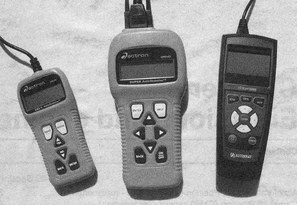
2. With the advent of the Federally mandated emission control system known as On-Board Diagnostics-II (OBD-II), specially designed scanners were developed. Several tool manufacturers have released OBD-II scan tools for the home mechanic (see illus tration).
2.2 Hand-held scan tools like these can extract computer codes and also perform diagnostics
OBD-ll system general description
3. All vehicles covered by this manual are equipped with the OBD-II system. This system consists of the on-board computer, known as the Powertrain Control Module (PCM), and information sensors that monitor various functions of the engine and send a constant stream of data to the PCM during engine operation. Unlike earlier on-board diagnostics systems, the OBD-II system doesn’t just monitor everything, store Diagnostic Trouble Codes (DTCs) and illuminate a Check Engine light or Malfunction Indicator Light (MIL) when there’s a problem. This warning light was referred to as the «Check Engine» light prior to OBD-II, and many do-it-yourselfers and professional technicians still use this term. However, its name was changed to «Malfunction Indicator Light,» or simply «MIL,» as part of the Society of Automotive Engineers’ standard terminology that was introduced in 1996 to encourage all manufacturers to use the same terms when referring to the same components. So in this manual we will refer to this warning light as the Malfunction Indicator Light, or MIL.
4. The PCM is the brain of the electronically controlled OBD-II system. It receives data from a number of information sensors and switches. Based on the data that it receives from the sensors, the PCM constantly alters engine operating conditions to optimize drivability, performance, emissions and fuel economy. It does so by turning on and off and by controlling various output actuators such as relays, solenoids, valves and other devices. The PCM can only be accessed with an OBD-II scan tool plugged into the 16-pin Data Link Connector (DLC), which is located underneath the driver’s end of the dashboard, near the steering column.
5. If your vehicle is still under warranty, virtually every fuel, ignition and emission control component in the OBD-II system is covered by a Federally mandated emissions warranty that is longer than the warranty covering the rest of the vehicle. Vehicles sold in California and in some other states have even longer emissions warranties than other states. Read your owner’s manual for the terms of the warranty protecting the emission-control systems on your vehicle. It isn’t a good idea to do-it-yourself at home while the vehicle emission systems are still under warranty because owner-induced damage to the PCM, the sensors and/or the control devices might VOID this warranty. So as long as the emission systems are still under warranty, take the vehicle to a dealer service department if there’s a problem.
Information sensors
6. Accelerator Pedal Position (APP) sensor – The APP sensor is located on the accelerator pedal. It provides the PCM with information about the angle of the accelerator pedal at all times.
7. Camshaft Position (CMP) sensor – The CMP sensor produces a signal that the PCM uses to monitor the position of the camshaft. The CMP sensor is positioned next to a tone wheel mounted on the front of the camshaft. On diesel engines, the tone wheel is located on the timing gear. The tone wheel has notches machined into it. When the engine is operating, the CMP sensor receives a 5-volt signal from the PCM (ECM on diesels), then sends a 0.3-volt signal back to the PCM/ ECM that switches to 5 volts every time one of the notches passes by it. This data enables the PCM to determine the position of the camshaft (and therefore the valve train) so that it can time the firing sequence of the fuel injectors. The PCM also uses the signal from the CMP sensor and the signal from the Crankshaft Position (CKP) sensor to distinguish between fuel injection and spark timing. On diesel engines, the CMP sensor’s signal is used primarily for starting; once the engine is running, the Powertrain Control Module (PCM) uses the CMP as a back-up sensor for engine speed (the CKP sensor is the primary engine speed indicator for a running diesel engine).
On 3.7L V6 and 4.7L V8 engines, the CMP sensor is located on the outer side of the front end of the right cylinder head, just ahead of the exhaust manifold. On Hemi engines, the CMP sensor is located on the upper right side of the timing chain cover. On diesel engines, the CMP sensor is located on the left rear of the timing gear cover.
8. Crankshaft Position (CKP) sensor -Like the CMP sensor, the CKP sensor is also a Hall effect device. The CKP sensor uses a tone wheel with notches machined into it to flip the CKP sensor’s output from 0.3 volt to 5 volts every time a notch passes by it. On gasoline engines, the tone wheel for the CKP sensor is mounted at the rear end of the crankshaft. The tone wheel for the CKP sensor on diesel engines is located on the front end of the crankshaft, behind the harmonic balancer. The PCM uses data from the CKP sensor to calculate engine speed and crankshaft position, which enables it to synchronize ignition timing with fuel injector timing, to control spark knock and to detect misfires.
On gasoline engines, the CKP sensor is located on the right rear side of the block. On diesel engines, the CKP sensor is located on the front left side of the engine, next to the harmonic balancer.
9. Engine Coolant Temperature (ECT) sensor – The ECT sensor is a Negative Temperature Coefficient thermistor (temperature-sensitive variable resistor). The resistance of the thermistor decreases as the coolant temperature increases, so the voltage output of the ECT sensor increases. The PCM uses this variable voltage signal to calculate the temperature of the engine coolant. The ECT sensor tells the PCM when the engine is sufficiently warmed up to go into closed-loop operation and helps the PCM control the air/ fuel mixture ratio and ignition timing. On 3.7L V6 and 4.7L V8 engines, the ECT sensor is located at the front of the intake manifold. On Hemi engines, the ECT sensor is located at the front of the block, under the air conditioning compressor. On diesel engines, the ECT sensor is located at the right front corner of the cylinder head, near the thermostat housing.
10. Fuel temperature sensor – The fuel temperature sensor is an integral part of the fuel heater and can be replaced only by replacing the fuel heater assembly (see Fuel and exhaust systems – diesel engine).
11. Inlet air temperature/pressure sensor - This dual-function sensor is used only on diesel engines. The inlet air temperature part of the sensor monitors ambient (outside) air temperature and the pressure part of the sensor monitors barometric pressure. The inlet air temperature/pressure sensor is located on the air filter housing cover.
12. Input Shaft Speed (ISS) sensor – The ISS sensor is a magnetic pick-up coil that generates a signal to the Transmission Control Module (TCM) that’s proportional to the speed of rotation of the input shaft. The TCM and PCM use this signal to determine the correct transmission gear ratio and to detect problems with the Vehicle Speed Sensor (VSS) signal. The TCM and PCM also compare the ISS signal to the VSS signal to determine whether the Torque Converter Clutch (TCC) is slipping, or is starting to slip. There are five transmissions used on the models in this book; the locations of the ISS sensor vary.
13. Intake Air Temperature (IAT) sensor - The IAT sensor is a Negative Temperature Coefficient (NTC) thermistor (temperature-sensitive variable resistor) that monitors the temperature of the air entering the engine and sends a variable voltage signal to the PCM (see the explanation for how an NTC-type thermistor works in the ECT sensor description above). The voltage signal from the IAT sensor is one of the inputs used by the PCM to determine injector pulse-width (the duration of each injector’s on-time) and to adjust spark timing. On 3.7L V6 and 4.7L V8 engines, the IAT sensor is located on the left side of the intake manifold. On Hemi engines, the IAT sensor is located on the front of the air resonator box. On diesel engines, the IAT sensor (which is one-half of the dual-function IAT/ MAP sensor) is located on top of the intake manifold.
14. Knock Sensor (KS) – The Knock Sensor (KS) is a piezoelectric crystal that oscillates in proportion to engine vibration. The oscillation of the crystal produces a voltage output that is monitored by the PCM, which retards the ignition timing when the oscillation exceeds a certain threshold. When the engine is operating normally, the Knock Sensor (KS) oscillates consistently and its voltage signal is steady. When detonation occurs, engine vibration increases, and the oscillation of the Knock Sensor (KS) exceeds a design threshold. Detonation is an uncontrolled explosion, after the spark occurs at the spark plug, which spontaneously combusts the remaining air/ fuel mixture, resulting in a pinging or slapping sound. If allowed to continue, the engine could be damaged. Knock sensors are used only on gasoline engines. These engines are equipped with two knock sensors. On 3.7L V6 and 4.7L V8 engines, the knock sensors are located on top of the block, under the intake manifold. On Hemi engines, the knock sensors are located on each side of the block, under the exhaust manifolds.
15. Manifold Absolute Pressure (MAP) sensor – Air density changes with altitude and the PCM needs to know the air density at all times. The MAP sensor monitors the pressure or vacuum downstream from the throttle plate, inside the intake manifold. The MAP sensor measures intake manifold pressure and vacuum on the absolute scale, from zero psi, not from sea-level atmospheric pressure (14.7 psi). The MAP sensor converts the absolute pressure into a variable voltage signal that changes with the pressure or vacuum. The PCM uses this signal to calculate intake manifold pressure or vacuum, engine load, injector pulse-width, spark advance, shift points, idle speed and deceleration fuel shut-off. On 3.7L V6 and 4.7L V8 engines, the MAP sensor is located on the front of the intake manifold. On Hemi engines, the MAP sensor is located on the front of the air resonator box. On diesel engines, the MAP sensor (which is one-half of the dual-function IAT/MAP sensor) is located on top of the intake manifold.
16. Output Shaft Speed (OSS) sensor -The OSS sensor is a magnetic pick-up coil that generates an output to the Transmission Control Module (TCM) that’s proportional to the speed of rotation of the output shaft. The TCM and PCM use this signal to determine the correct transmission gear ratio, and to detect problems with the Vehicle Speed Sensor (VSS) signal. The TCM and PCM also compare the OSS signal to the VSS signal to determine whether the Torque Converter Clutch (TCC) is slipping or is starting to slip. The OSS is located on the rear of the transmission on all models.
17. Oxygen sensors – The PCM uses the voltage signal from the upstream oxygen sensor to maintain an air/fuel ratio of 14.7:1 by constantly adjusting the on-time of the fuel injectors. There are two oxygen sensors: the upstream sensor is located on the exhaust manifold and a downstream oxygen sensor is located behind the catalyst.
18. Throttle Position (TP) sensor – The TP sensor is a potentiometer that receives constant voltage input from the PCM and sends back a voltage signal that varies in relation to the opening angle of the throttle plate inside the throttle body. The PCM uses this, along with information from other sensors, to calculate injector pulse width (the interval of time during which an injector solenoid is energized by the PCM). This sensor is an integral part of the throttle body’s ETC motor assembly and cannot be serviced separately. Diesel engines don’t have a TP sensor because they don’t have a throttle body (or a throttle plate).
19. Transmission Range (TR) sensor - The TR sensor is located at the end of the manual shaft, on the side of the automatic transmission. The TR sensor performs the same functions as a Park/Neutral Position switch: it prevents the engine from starting in any gear other than Park or Neutral, and it closes the circuit for the back-up lights when the shift lever is moved to Reverse. The TR sensor is also connected to the PCM, which sends a voltage signal to the TR sensor. The PCM monitors the voltage output signal from the switch, which corresponds to the position of the manual lever. Thus the PCM is able to determine the gear selected and is able to determine the correct pressure for the electronic pressure control system of the transmission. On most transmissions, the TR sensor is an integral part of the shift solenoid module, which is on top of the valve body, inside the transmission. Replacing the TR sensors on these transmissions is beyond the scope of the home mechanic.
20. Vehicle Speed Sensor (VSS) – The speed sensor is a magnetic pick-up coil that monitors output shaft rotating speed on automatic transmissions. The sensor is positioned over the park gear. When the vehicle is moving the park gear lugs rotate past the speed sensor, which generates a pulsing voltage. The frequency of this voltage increases as the speed goes up. This signal is processed by the Transmission Control Module (TCM), which shares this data with the PCM. The TCM and PCM use the speed sensor signal to calculate vehicle speed. The speed sensor is located on the overdrive gear case.
Output actuators
21. EVAP canister purge solenoid – The EVAP canister purge solenoid is a PCMcontrolled solenoid that controls the purging of evaporative emissions from the EVAP canister to the intake manifold. The EVAP purge solenoid is never turned on during cold start warm-ups or during hot start time delays. But once the engine reaches a specified temperature and enters closed-loop operation, the PCM will energize the canister purge solenoid between 5 and 10 times a second. When the solenoid is energized by the PCM, it allows the fuel vapors that are stored in the EVAP canister to be drawn into the intake manifold, where they’re mixed with intake air, then burned along with the normal air/fuel mixture, under certain operating conditions. The PCM regulates the flow rate of the vapors by controlling the pulse-width of the solenoid (the length of time during which the solenoid is turned on) in accordance with operating conditions. The EVAP canister purge solenoid is located under the engine compartment fuse and relay box and the (left) battery tray.
22. EVAP Natural Vacuum Leak Detection (NVLD) system – These vehicles use a Natural Vacuum Leak Detection (NVLD) system. The NVLD system is based on the principle that the pressure inside a sealed container (such as the EVAP system) will change if the temperature changes; if the temperature goes up, so does the pressure. If during a leak test the PCM notes that the pressure inside the EVAP system isn’t proportional to the temperature, it sets a Diagnostic Trouble Code (DTC) for a leak. The NVLD unit is located in front of the EVAP canisters, which are located under the vehicle in front of the fuel tank.
23. Fuel injectors – The fuel injectors, which spray fuel into the intake ports, are coils under PCM control. The injectors are installed between the fuel rail and the intake ports. For more information about the injectors, see Fuel and exhaust systems – gasoline engines Fuel and exhaust systems – diesel engine .
24. Ignition coils – The ignition coils are under the control of the Powertrain Control Module (PCM). For more information about the ignition coils, refer to Chapter Engine electrical systems .
Obtaining and clearing Diagnostic Trouble Codes (DTCs)
25. All models covered by this manual are equipped with on-board diagnostics. When the PCM recognizes a malfunction in a monitored emission control system, component or circuit, it turns on the Malfunction Indicator Light (MIL) on the dash. The PCM will continue to display the MIL until the problem is fixed and the Diagnostic Trouble Code (DTC) is cleared from the PCM’s memory. You’ll need a scan tool to access any DTCs stored in the PCM. Before outputting any DTCs stored in the PCM, thoroughly inspect ALL electrical connectors and hoses. Make sure that all electrical connections are tight, clean and free of corrosion. And make sure that all hoses are correctly connected, fit tightly and are in good condition (no cracks or tears). Also, make sure that the engine is tuned up. A poorly running engine is probably one of the biggest causes of emission-related malfunctions. Often, simply giving the engine a good tune-up will correct the problem.
Accessing the DTCs
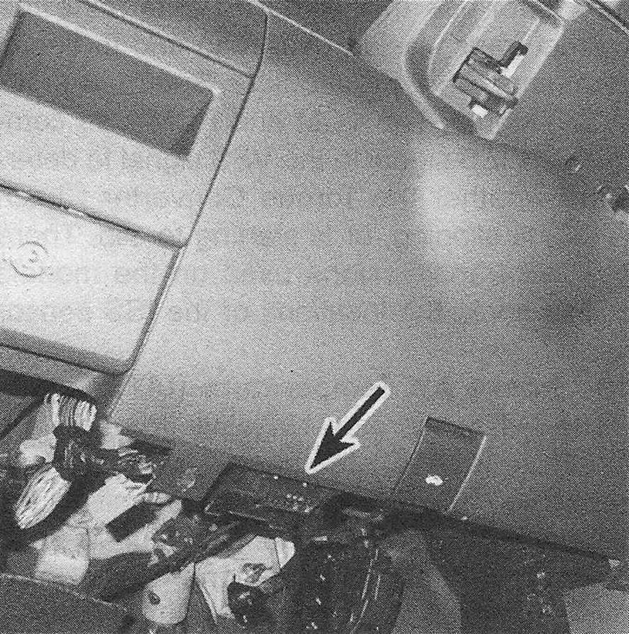
26. On the vehicles covered in this manual, the Diagnostic Trouble Codes (DTCs) can only be accessed with a scan tool. Plug the connector of the scan tool into the Data Link Connector (DLC) or diagnostic connector, which is located under the lower edge of the dash, just to the left of the hood release handle (see illustration). Then follow the instructions included with the scan tool to extract the DTCs.
2.26 The Data Link Connector (DLC), or diagnostic connector, is located under the instrument panel
27. Once you have outputted all of the stored DTCs, look them up on the accompanying DTC chart.
28. After troubleshooting the source of each DTC, make any necessary repairs or replace the defective component (s).
Clearing the DTCs
29. Clear the DTCs with the scan tool in accordance with the instructions provided by the scan tool’s manufacturer.
Diagnostic Trouble Codes
30. The accompanying tables are a list of the Diagnostic Trouble Codes (DTCs) that can be accessed by a do-it-yourselfer working at home (there are many more DTCs available to professional service technicians with proprietary scan tools and software, but those codes cannot be accessed by a generic scan tool). If, after you have checked and repaired the connectors, wire harness and vacuum hoses (if applicable) for an emission-related system, component or circuit, the problem persists, have the vehicle checked by a dealer service department.
OBD-ll Diagnostic Trouble Codes (DTCs)
Note: Not all trouble codes apply to all models.