Knock sensors – replacement
1. Disconnect the cable (s) from the negative battery terminal(s) (see Engine electrical systems).
3.6L V6 engine
Note: There are two knock sensors, both located below the lower intake manifold area. The sensor closest to the front of the engine is Sensor 1 and the other is Sensor 2.
2. Remove the intake manifolds (see 3.6L V6 engine).
3. Disconnect the electrical connector (s), then remove the sensor(s) mounting bolt(s).
4. Remove the sensor (s) from the valley between the cylinder banks.
5. Installation is the reverse of removal. Tighten the knock sensor mounting bolt (s) to the torque listed in this Chapter’s Specifications.
3.7L V6 and 4.7L V8 engines
6. Remove the intake manifold (see 3.7L V6 and 4.7L V8 engines).
7. Disconnect the knock sensor electrical connector, which is located at the rear of the engine, behind the intake manifold. Note: If you can’t find the knock sensor electrical connector, wait until you have removed the intake manifold. Then locate the two knock sensors and trace their leads back to this common connector.
8. Remove the knock sensor mounting bolt (s) and remove the knock sensor(s). Note: Any foam strips on the knock sensor mounting bolt threads are used to retain the bolts during vehicle assembly at the manufacturing plant. They have no other purpose. They are not some form of adhesive, thread sealant or locking compound. Do NOT use any type of adhesive, thread sealant or locking compound when installing these bolts again.
9. Make sure that the holes for the knock sensor mounting bolts are thoroughly cleaned before installing the bolts. Note: On 3.7L V6 engines, the left knock sensor is identified by an identification tag (LEFT); it also has a larger mounting bolt. Do NOT switch the knock sensors – do not install the left knock sensor in the right sensor mounting position and vice versa. The PCM assumes that the knock sensors are installed in their correct locations. Switching the sensor locations will confuse the PCM and cause it to set a Diagnostic Trouble Code.
10. Installation is otherwise the reverse of removal. Tighten the knock sensor mounting bolts to the torque listed in this Chapter’s Specifications. Caution: Over- or under-tightening the knock sensor mounting bolts will affect knock sensor performance, which might affect the PCM’s spark control ability.
Hemi engines
Note: There are two knock sensors. One is located on the left side of the block, below the exhaust manifold, and the other is located in the same place on the right side of the block.
11. Raise the front of the vehicle and place it securely on jackstands.
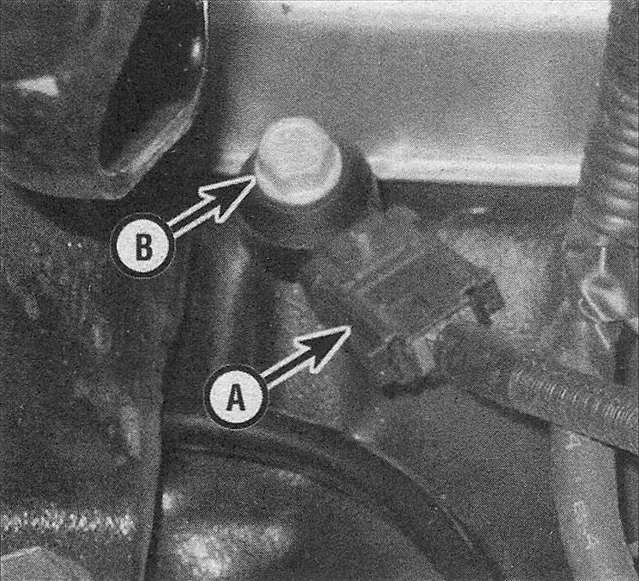
12. Disconnect the electrical connector from the knock sensor (see illustration).
9.12 Disconnect the knock sensor electrical connector (A) and remove the knock sensor mounting bolt (B) (Hemi engine)
13. Remove the knock sensor mounting bolt and remove the knock sensor from the engine. Note: Any foam strips on the knock sensor mounting bolt threads are used to retain the bolts during vehicle assembly at the manufacturing plant. They have no other purpose. They are not some form of adhesive, thread sealant or locking compound. Do NOT use any type of adhesive, thread sealant or locking compound when installing these bolts again.
14. Installation is the reverse of removal. Tighten the knock sensor mounting bolts to the torque listed in this Chapter’s Specifications. Caution: Over- or under-tightening the knock sensor mounting bolts will affect knock sensor performance, which might affect the PCM’s spark control ability.