Valve cover – removal and installation
Note: The injector wiring harness is integrated into the valve cover gasket. Use care to avoid damaging the wiring.
1. Disconnect the cables from the negative terminals of the batteries (see Engine electrical systems).
2. Remove the four bolts and the engine cover.
3. Remove the oil filler cap.
4. Remove the bolts from the breather cover.
5. Remove the Closed Crankcase Ventilation (CCV) cover and the breather filter (see Tune-up and routine maintenance).
6. Disconnect the CCV tube at the Crankcase Depression Regulator (CDR) valve (at the right rear of the valve cover)
7. Disconnect the crankcase pressure sensor from the left rear of the valve cover.
8. Remove the two CCV drain hoses from the left side of the valve cover.
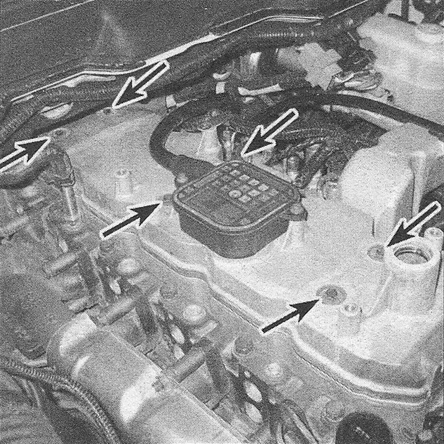
9. Remove the valve cover bolts, then remove the valve cover (see illustration).
4.9 Valve cover bolt locations
10. Remove the nuts that secure the valve cover gasket/wiring harness and disconnect the wiring harness from the injectors. Remove the gasket/wiring harness.
11. Clean the gasket mating surfaces of the cylinder head and the valve cover. Wipe off the gasket and inspect its condition. The gasket and isolators (the rubber grommets for the valve cover bolts) can be reused if they’re not hardened, cracked or otherwise damaged. If an isolator or the valve cover gasket is cracked, replace it to avoid leaks.
12. Installation is the reverse of removal. Make sure the gasket is installed properly (some are marked TOP FRONT). Tighten the bolts a little at a time, starting with the center bolts, to the torque listed in this Chapter’s Specifications.