Front axle assembly (4WD models) – removal and installation
Independent front suspension
1. Loosen the front wheel lug nuts. Raise the front of the vehicle and support it with jackstands placed under the frame rails.
2. Detach the vent tube from the axle and seal it. Caution: Make sure that you perform this Step now and not while the axle assembly is being removed. If you wait, and the vent gets filled with oil, it may be ruined and damage the entire axle.
3. Remove the driveaxles (Driveaxle (4WD models with independent front suspension) – removal and installation).
4. Disconnect the driveshaft from the differential pinion flange and support it out of the way with a piece of wire or rope (Driveshaft(s) – removal and installation). Also remove the companion flange from the differential. Note: Mark the positions of the flange and the nut so they can be installed in their original positions.
5. Remove the skid plate.
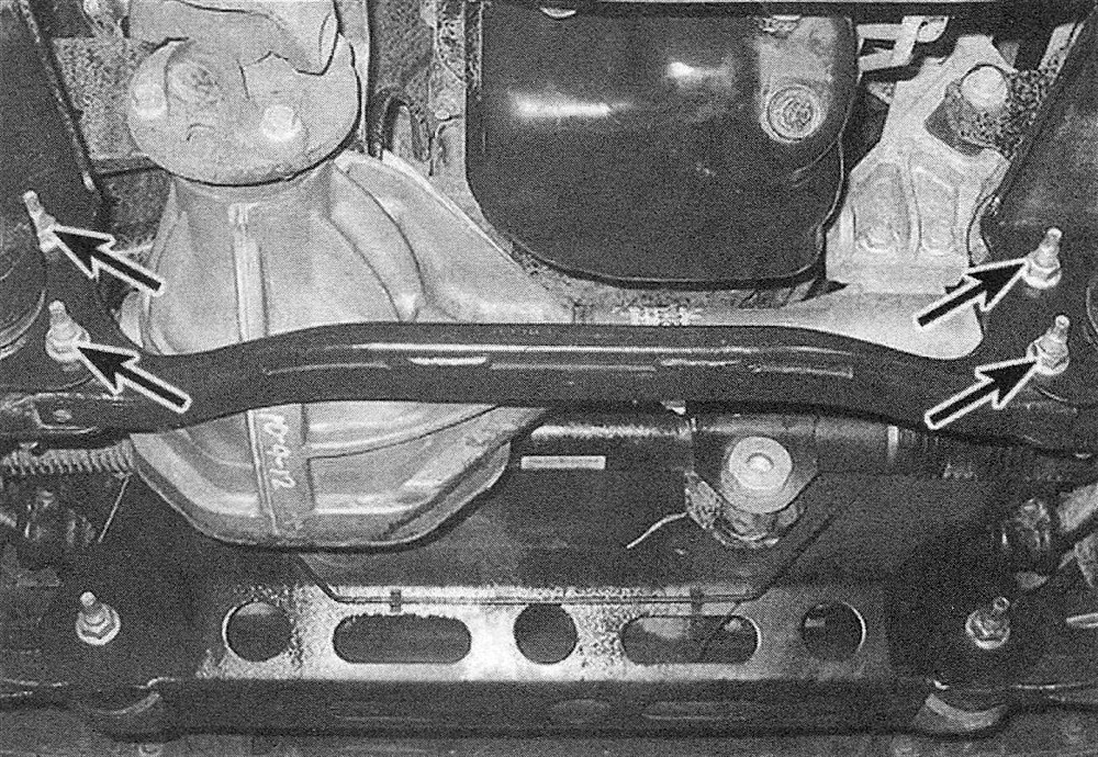
6. Remove the suspension crossmember (see illustration).
22.6 Remove the crossmember mounting bolts
7. Disconnect the wiring from the stabilizer bar disconnect device.
8. Support the axle assembly with a floor jack under the differential.
9. Remove any remaining interfering wiring harness clips.
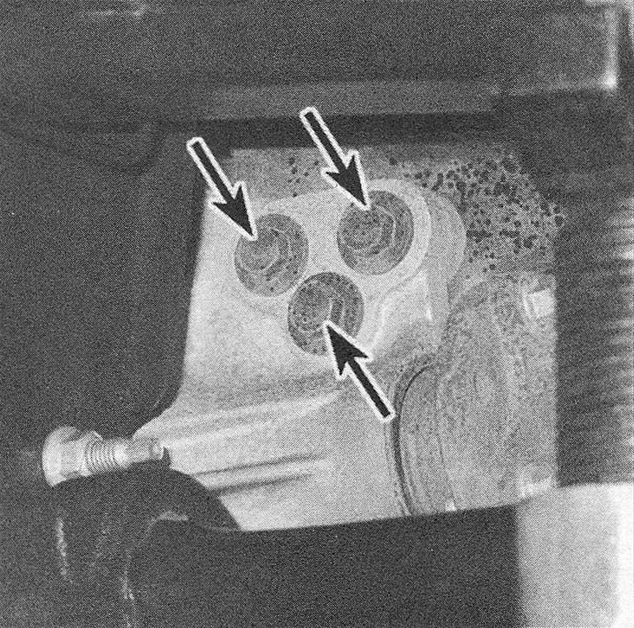
10. Remove the axle assembly pinion mounting bolts (see illustration). Also remove the bolts from the axle shaft tube and the differential housing-to-engine mounting bolts.
22.10 Remove the axle housing pinion mounting bolts (shown), then the axle tube mounting bolts and the differential housing-to-engine bolts
11. Lower the jack slowly, then roll the axle assembly from under the vehicle.
12. Installation is the reverse of removal.
Solid axle
13. Loosen the front wheel lug nuts. Raise the vehicle and support it securely with jackstands positioned under the frame rails. Remove the front wheels.
14. Remove the brake calipers and discs (see Brakes) and disconnect the ABS wheel speed sensors.
15. Disconnect the vent hose and the brake hose bracket.
16. Mark the driveshaft to the companion flange, then disconnect it from the differential pinion flange. Support the driveshaft out of the way with a piece of wire or cord (Driveshaft(s) – removal and installation).
17. Disconnect the stabilizer bar links from the axle brackets (see Suspension and steering systems).
18. Disconnect the shock absorbers from the axle brackets.
19. Disconnect the tie-rod and drag link from the steering knuckle (see Suspension and steering systems). Support the axle assembly with two floor jacks, one positioned under the differential and one positioned under the long axle tube.
20. Disconnect the track bar from the axle bracket (see Suspension and steering systems).
21. On heavy-duty models, disconnect the vibration damper from the axle bracket.
22. Mark the relationship of the alignment cams to ensure proper reassembly, then remove the bolts and disconnect the control arms from the axle bracket.
23. Lower the jacks and remove the axle from under the vehicle.
24. Installation is the reverse of removal. Tighten all bolts to the torque listed in this Chapter’s Specifications and in the Specifications in Chapters 9 and 10.