Driveshaft(s) – removal and installation
Note: The manufacturer recommends replacing driveshaft fasteners with new ones when installing the driveshaft.
Rear driveshaft Removal
Note: Where a two-piece driveshaft is involved, the rear shaft must be removed before the front shaft.
1. Raise the vehicle and support it securely on jackstands.
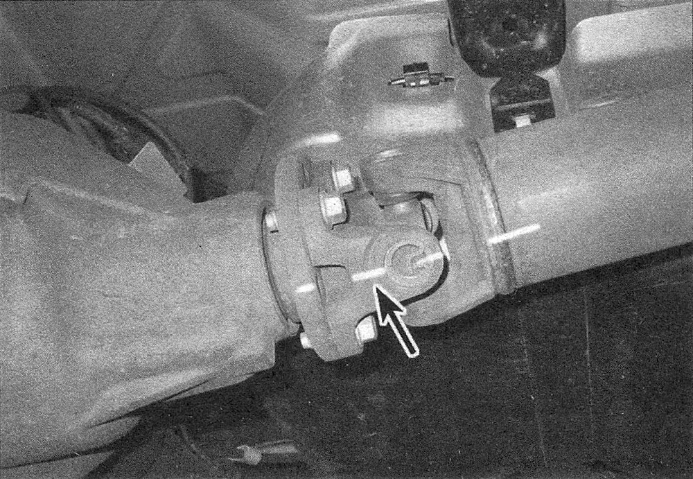
2. Use chalk or a scribe to mark the relationship of the driveshaft to the differential axle assembly mating flange or yoke. This ensures correct alignment when the driveshaft is reinstalled (see illustration).
9.2 Mark the relationship of the driveshaft to the pinion flange or yoke
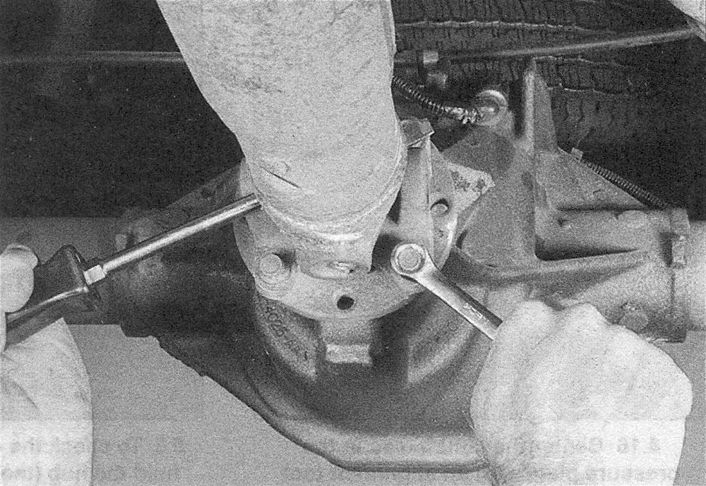
3. Remove the bolts securing the driveshaft flange or universal joint clamps to the differential pinion flange or yoke (see illustration). Turn the driveshaft (or wheels) as necessary to bring the bolts into the most accessible position.
9.3 Insert a large screwdriver or prybar through the driveshaft or pinion yoke as shown, to prevent the shaft from turning when you loosen the fasteners
4. Pry the universal joint away from its mating flange or yoke and remove the shaft from the flange. Be careful not to let the caps fall off of the universal joint (which would cause contamination and loss of the needle bearings).
5. Lower the rear of the driveshaft. If the driveshaft is a one-piece unit, slide the front end of the driveshaft out of the transmission extension housing; if it’s a two-piece driveshaft, mark the relationship of the center support bearing to the support bracket, then unbolt the center support bearing and slide the front end of the front driveshaft out of the extension housing.
6. Wrap a plastic bag over the extension housing and hold it in place with a rubber band. This will prevent loss of fluid and protect against contamination while the driveshaft is out.
Installation
7. Remove the plastic bag from the transmission or transfer case extension housing and wipe the area clean. Inspect the oil seal carefully. If it’s leaking, now is the time to replace it (see Manual transmission).
8. Inspect the center support bearing, if equipped. If it’s rough or noisy, replace it (Driveshaft center support bearing – removal and installation).
9. Insert the front end of the driveshaft assembly into the transmission or transfer case extension housing.
10. If the driveshaft is a one-piece unit, raise the rear of the driveshaft into position, checking to be sure the marks are in alignment. If not, turn the pinion flange until the marks line up.
11. If the driveshaft is a two-piece unit, raise the center support bearing and bolt it loosely into place. Raise the rear end of the rear shaft into position and make sure the alignment marks are in alignment; if not, turn the pinion flange until they are.
12. Remove the tape securing the bearing caps and install the clamps, if equipped, and fasteners. Tighten the center support bearing bolts to the torque listed in this Chapter’s Specifications.
Front driveshaft (4WD models)
13. Raise the vehicle and support it securely on jackstands.
14. If equipped, remove the skid plate.
15. If necessary, remove the exhaust crossover pipe.
16. Use chalk or a scribe to mark the relationship of the driveshaft to the differential axle assembly mating flange or yoke (see illustration 9.2). This ensures correct alignment when the driveshaft is reinstalled.
17. Remove the bolts and straps that secure the front end of the driveshaft to the differential mating flange or yoke.
18. On models equipped with a transfer case flange, make alignment marks on the driveshaft and transfer case flanges. Unbolt the flange that secures the driveshaft universal joint to the transfer case and differential, then remove the driveshaft.
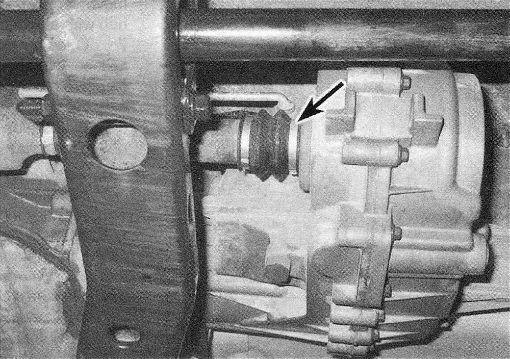
19. On 1500 models, remove the dust boot clamp, then slide the end of the driveshaft out of the transfer case (see illustration).
9.19 Remove the dust boot clamp, then slide the end of the driveshaft out of the transfer case (4WD 1500 models)
20. Installation is the reverse of removal. If the shaft cannot be lined up due to the components of the differential or transfer case having been rotated, put the vehicle in Neutral or rotate one wheel to allow the original alignment to be achieved. Make sure the universal joint caps are properly placed in the flange seat. Tighten the fasteners to the torque listed in this Chapter’s Specifications.