Driveaxle boot – replacement
Note: If the CV joints exhibit wear, indicating the need for an overhaul (usually due to torn boots), explore all options before beginning the job. Complete rebuilt driveaxles may be available on an exchange basis, which eliminates a lot of time and work. Whatever is decided, check on the cost and availability of parts before disassembling the joints.
1. Loosen the wheel lug nuts. Raise the vehicle and support it securely on jackstands, then remove the wheel.
2. Remove the driveaxle (Driveaxle (4WD models with independent front suspension) – removal and installation).
Inner CV joint Disassembly
3. Mount the driveaxle in a bench vise with wood blocks to protect it. Caution: Do not overtighten the vise.
4. Remove the boot retaining clamps and slide the inner boot back onto the shaft.
5. Pull the inner CV joint housing off the shaft and tripod.
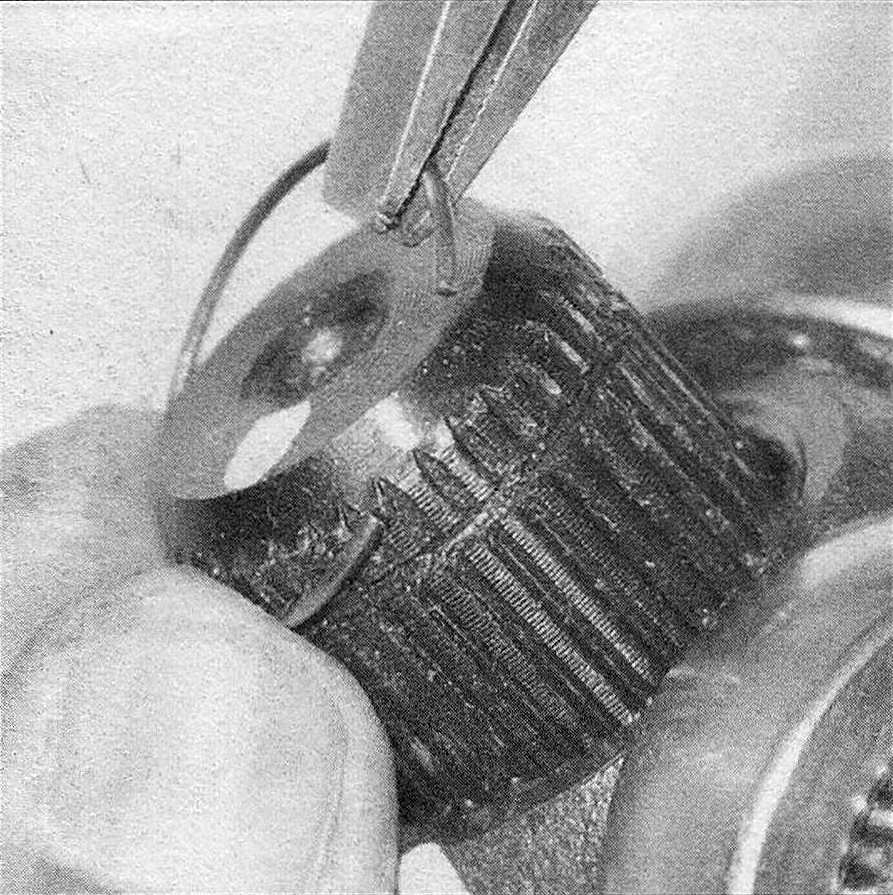
6. Use a pair of snap-ring pliers and remove the snap-ring from the end of the shaft (see illustration).
14.6 Remove the snap-ring from the groove in the end of the axleshaft
7. Mark the end of the shaft and the tripod, then remove the tripod from the shaft.
8. Remove the boot from the shaft.
9. Clean the housing and the tripod with solvent.
10. Check the tripod components and the housing for excessive wear and/or damage.
11. If any components are worn or damaged, the entire joint must be replaced.
Assembly
12. Wrap the splines of the shaft with tape to prevent damage to the boot, then install the small boot clamp and boot onto the shaft (see illustration).
14.12 Wrap the driveshaft splines with tape to prevent damaging the boot as it’s slid onto the shaft
13. Install the tripod onto the end of the shaft, with the mark you made facing the end of the shaft (and aligned with the mark on the shaft).
14. Install the snap-ring, making sure it is completely seated in its groove.
15. Apply CV joint grease to the tripod and interior of the housing. Note: If grease was not included with the new boot, obtain some CV joint grease – don’t use any other type of grease.
16. Apply the remainder of the grease into the boot, then insert the shaft and tripod into the housing.
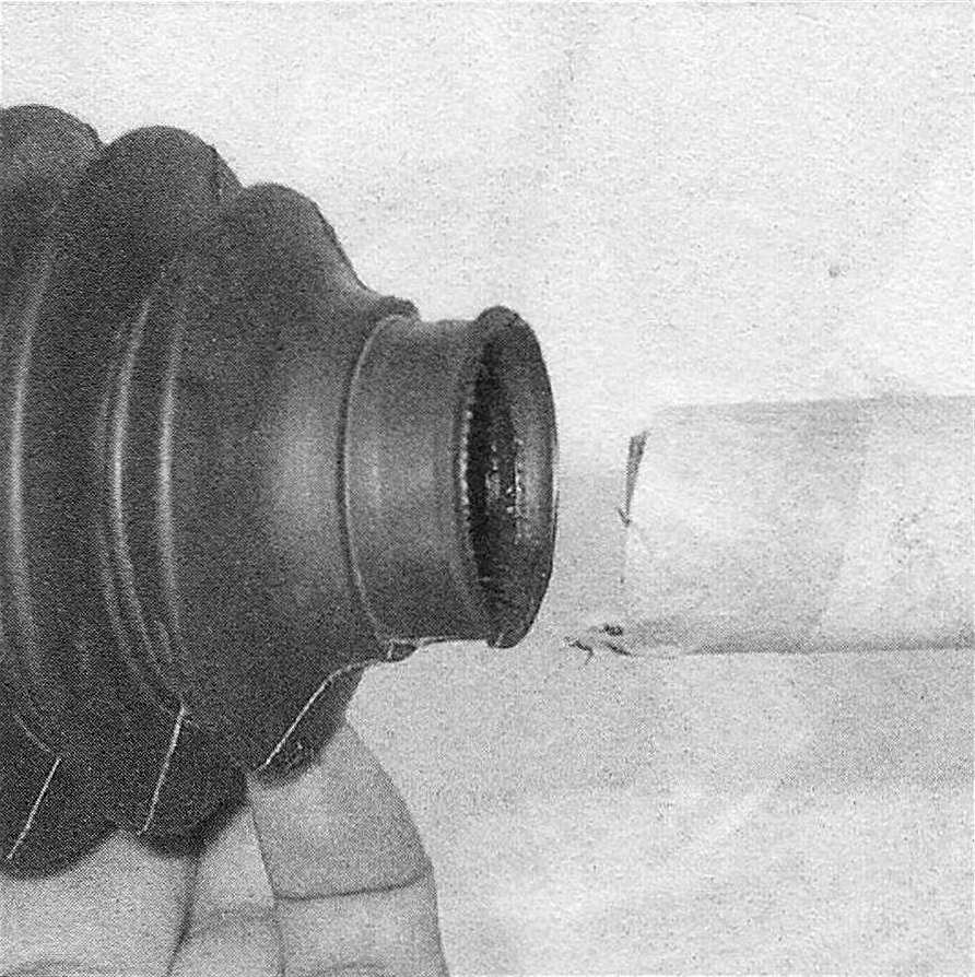
17. Position the large-diameter end of the boot over the edge of the housing and seat the lip of the boot into the locating groove at the edge of the housing. Insert the lip of the small-diameter end of the boot into the locating groove on the shaft.
18. Adjust the length of the joint by positioning it mid-way through its travel.
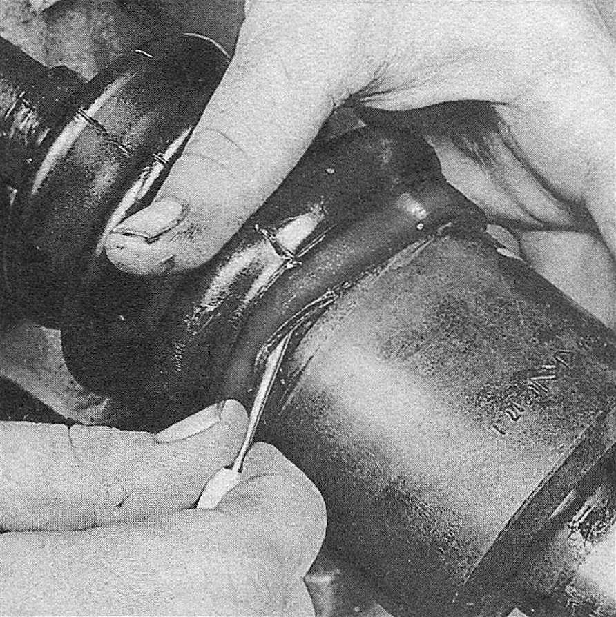
19. Insert a small screwdriver between the boot and the housing to equalize the pressure inside the boot (see illustration)
14.19 After positioning the joint mid-way through its travel, equalize the pressure inside the boot by inserting a small, dull screwdriver between the boot and the CV joint housing
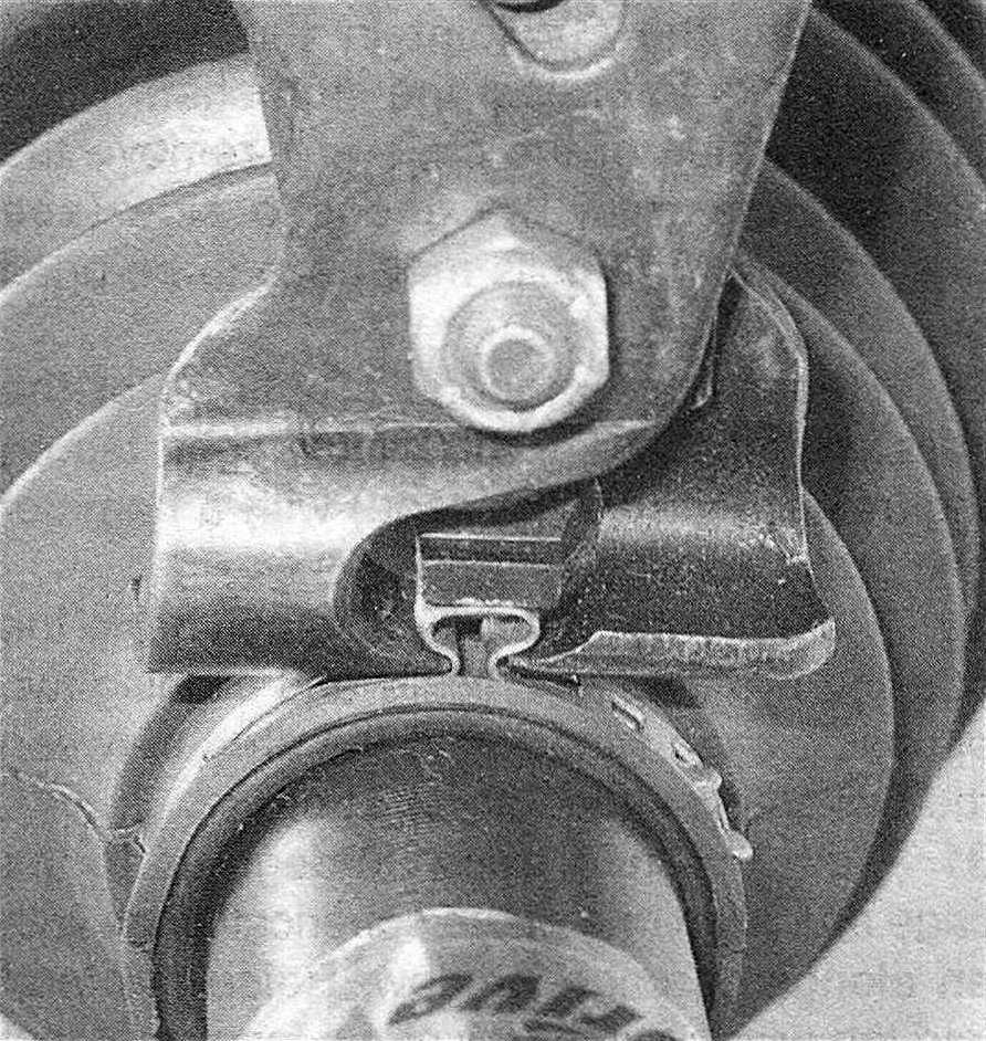
20. Tighten the boot clamps (see illustration).
14.20 Depending on the type of clamps furnished with the replacement boot, you’ll most likely need a special pair of clamp tightening pliers (most auto parts stores carry these)
Outer CV joint Disassembly
21. Mount the axleshaft in a vise with wood blocks to protect it, remove the boot clamps and push the boot back.
22. Wipe the grease from the joint.
23. Using a pair of snap-ring pliers, expand the snap-ring retaining the outer joint to the shaft, then remove the joint (see illustration).
14.23 After expanding the snap-ring, the outer joint assembly can be removed
24. Slide the boot off the driveaxle.
25. Clean the axle spline area and inspect for wear, damage, corrosion and broken splines.
26. Clean the outer CV joint bearing assembly with a clean cloth to remove excess grease.
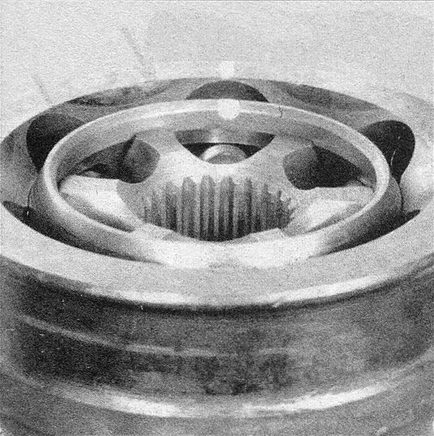
27. Mark the relative position of the bearing cage, inner race and housing (see illustration).
14.27. Mark the bearing cage, inner race and housing relationship after removing the grease
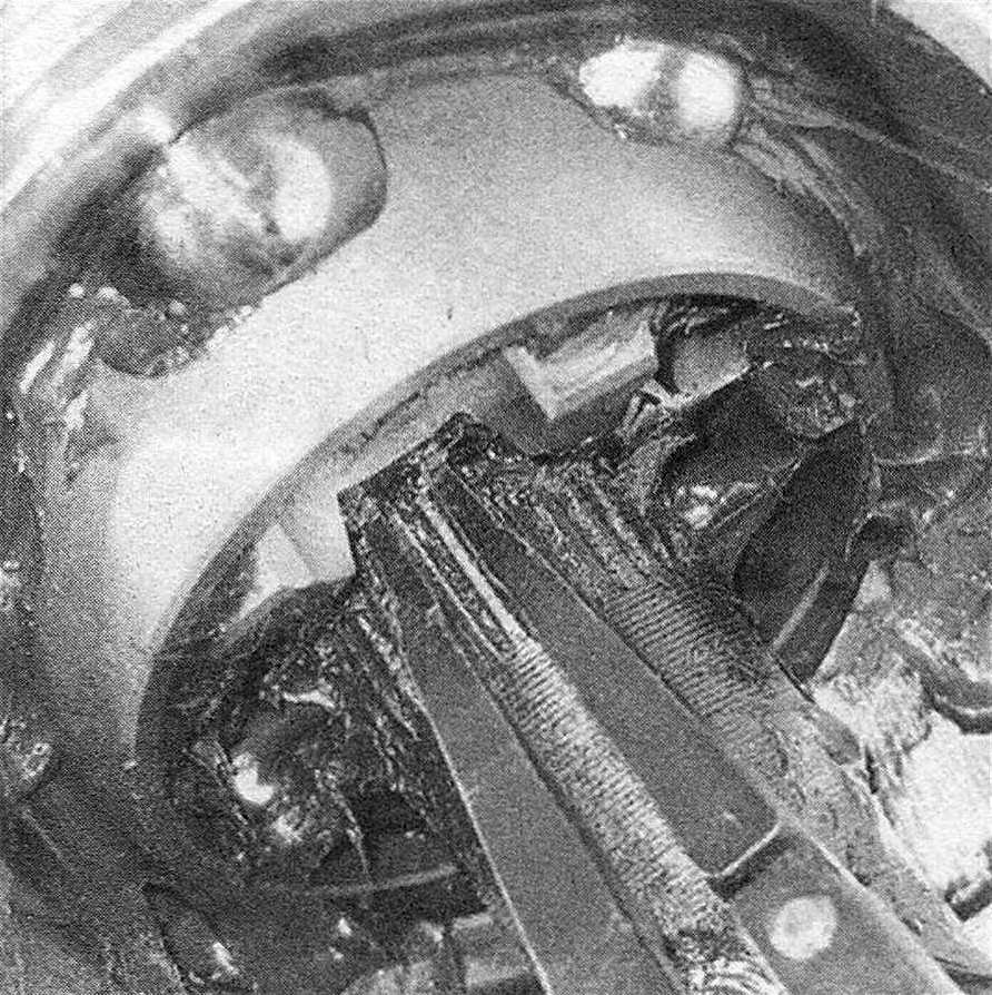
28. Mount the CV joint in the vise with wood blocks to protect the stub shaft. Push down one side of the cage and remove the ball bearing from the opposite side (see illustration). The balls may have to be pried out.
14.28 With the cage and inner race tilted, the balls can be removed one at a time
29. Repeat this procedure until all of the balls are removed. If the joint is tight, tap on the inner race (not the cage) with a hammer and brass drift.
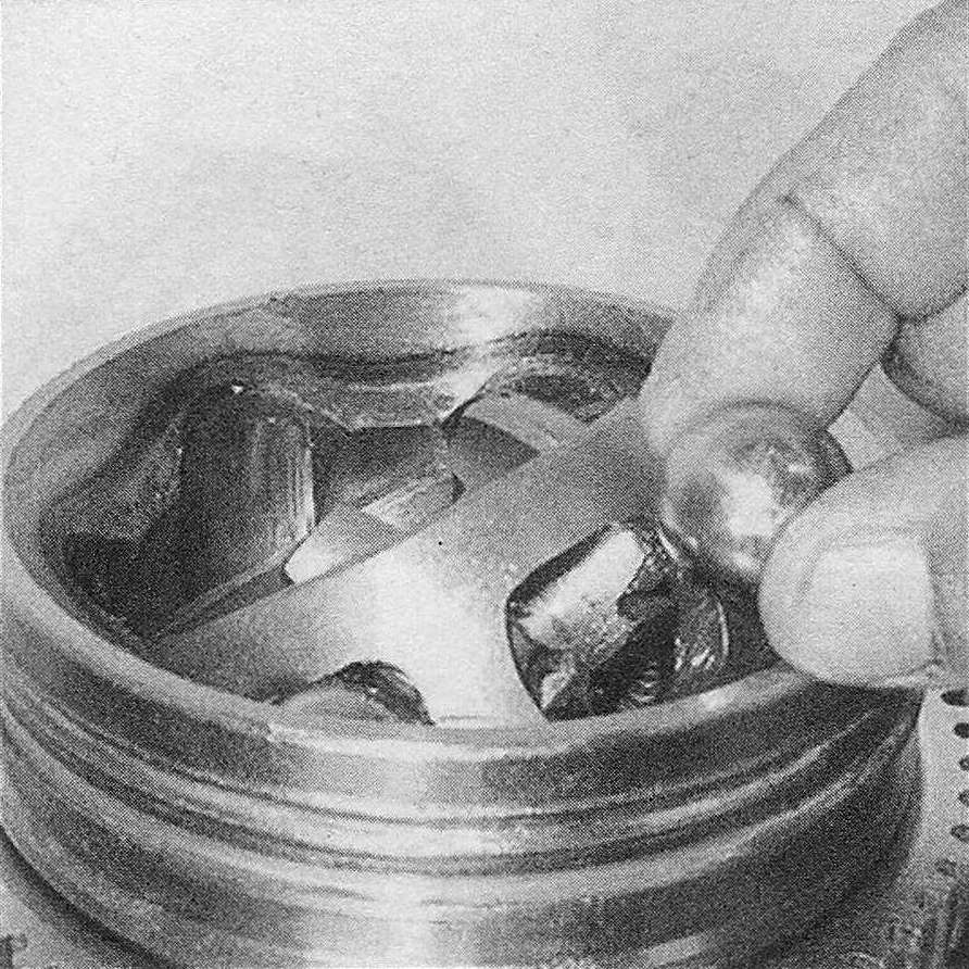
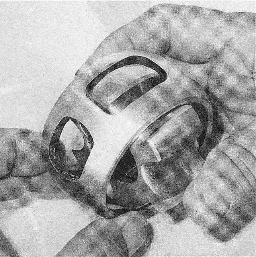
30. Remove the bearing assembly from the housing by tilting it vertically and aligning two opposing cage windows in the area between the ball grooves (see illustration).
14.30 Align one of the elongated windows in the cage with one of the lands on the housing (outer race), then rock the cage and inner race out of the housing
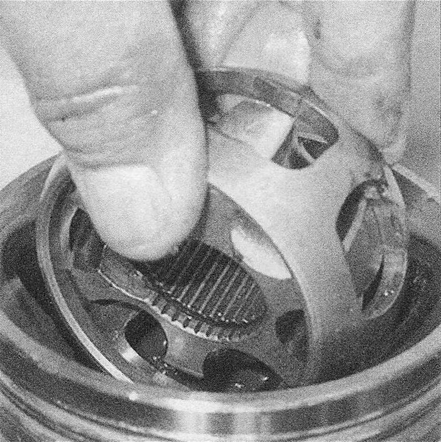
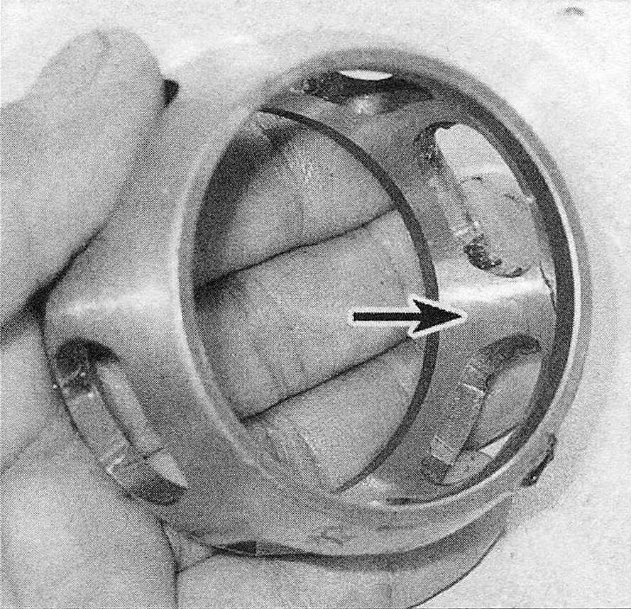
31. Turn the inner race 90-degrees to the cage and align one of the spherical lands with an elongated cage window. Raise the land into the window and swivel the inner race out of the cage (see illustration).
14.31 Tilt the inner race 90-degrees, align the race lands with the windows in the cage, then separate the two components
32. Clean all of the parts with solvent and dry them with compressed air (if available).
33. Inspect the housing, splines, balls and races for damage, corrosion, wear and cracks.
34. Check the inner race for wear and scoring. If any of the components are not serviceable, the entire CV joint assembly must be replaced with a new one (see illustrations).
14.34a Check the inner race lands and grooves for pitting and score marks
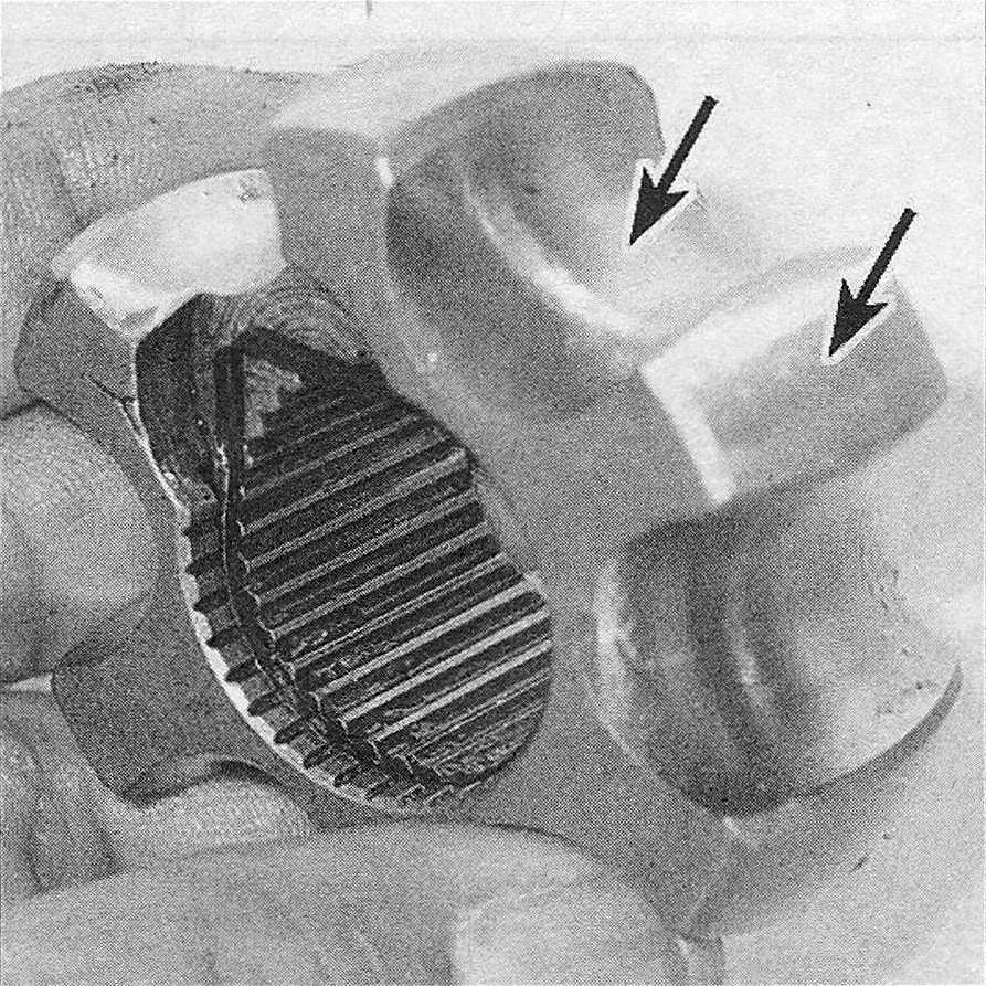
14.34b Check the cage for cracks, pitting and score marks (shiny spots are normal and don’t affect operation)
Assembly
35. Apply a thin film of oil to all CV joint components before beginning reassembly.
36. Align the marks and install the inner race in the cage so one of the race lands fits into the elongated window (see illustration 14.31).
37. Rotate the inner race into position in the cage and install the assembly in the CV joint housing, again using the elongated window for clearance (see illustration 14.30).
38. Rotate the inner race into position in the housing. Be sure the large counterbore of the inner race faces out. The marks made during disassembly should face out and be aligned.
39. Pack the lubricant from the kit into the ball races and grooves.
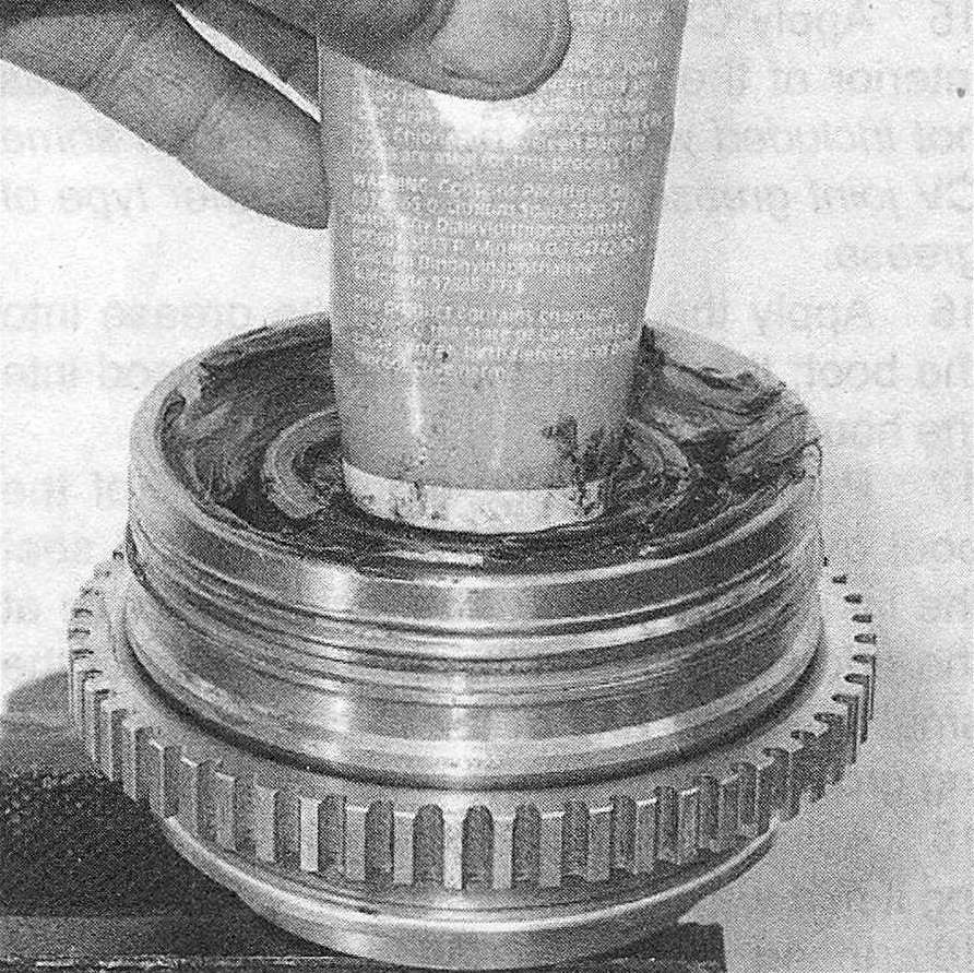
40. Install the balls into the holes, one at a time, until they are all in position. Fill the joint with grease through the splined hole, then insert a wooden dowel into the splined hole to force the grease into the joint (see illustration).
14.40 Apply grease through the splined hole, then insert a wooden dowel into the hole and push down – the dowel will force the grease into the joint
41. Place the driveaxle in the vise and slide the inner clamp and boot over it (wrap the shaft splines with tape to prevent damaging the boot) (see illustration 14.12).
42. Place the CV joint housing in position on the axle, align the splines and push it into place. If necessary, tap it on with a soft-face hammer. Make sure it is seated on the snap-ring by attempting to pull it from the shaft.
43. Make sure the boot is not distorted, then install and tighten the clamps (see illustration 14.20).