Relays – general information and testing
General information
1. Many electrical accessories in the vehicle utilize relays to transmit current to the component. If the relay is defective, the component won’t operate properly.
2. Most relays are located in the engine compartment fuse and relay box (see illustration 3.1).
3. Some relays are located in other parts of the vehicle, primarily in various wiring harnesses underneath the instrument panel.
4. If a faulty relay is suspected, it can be removed and tested using the procedure below or by a dealer service department or a repair shop. Defective relays must be replaced as a unit.
Testing
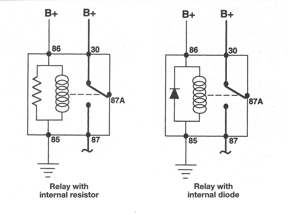
5. Most of the relays used in these vehicles are of a type often called ISO relays, which refers to the International Standards Organization. The terminals of ISO relays are numbered to indicate their usual circuit connections and functions. There are two basic layouts of terminals on the relays used in the vehicles covered by this manual (see illustrations).
5.5a Typical ISO relay designs, terminal numbering and circuit connections
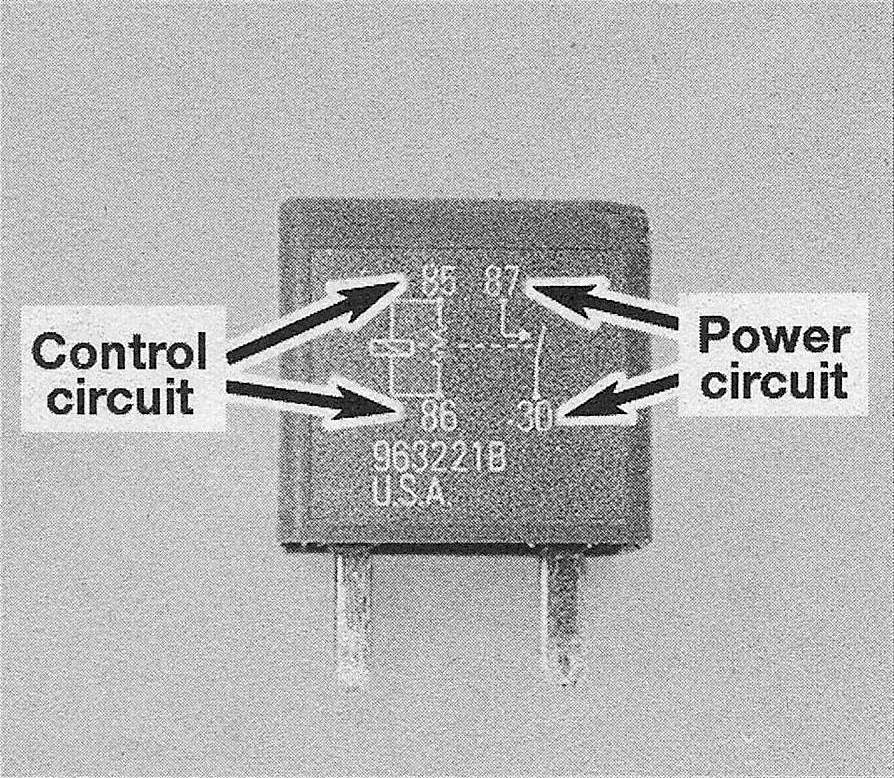
5.5b Most relays are marked on the outside to easily identify the control circuit and power circuits – this one is of the four-terminal type
6. Refer to the wiring diagram for the circuit to determine the proper connections for the relay you’re testing. If you can’t determine the correct connection from the wiring diagrams, however, you may be able to determine the test connections from the information that follows.
7. Two of the terminals are the relay control circuit and connect to the relay coil. The other relay terminals are the power circuit. When the relay is energized, the coil creates a magnetic field that closes the larger contacts of the power circuit to provide power to the circuit loads.
8. Terminals 85 and 86 are normally the control circuit. If the relay contains a diode, terminal 86 must be connected to battery positive (B+) voltage and terminal 85 to ground. If the relay contains a resistor, terminals 85 and 86 can be connected in either direction with respect to B+ and ground.
9. Terminal 30 is normally connected to the battery voltage (B+) source for the circuit loads. Terminal 87 is connected to the ground side of the circuit, either directly or through a load. If the relay has several alternate terminals for load or ground connections, they usually are numbered 87A, 87B, 87C, and so on.
10. Use an ohmmeter to check continuity through the relay control coil.
a) Connect the meter according to the polarity shown in the illustration for one check; then reverse the ohmmeter leads and check continuity in the other direction.
b) If the relay contains a resistor, resistance will be indicated on the meter, and should be the same value with the ohmmeter in either direction.
c) If the relay contains a diode, resistance should be higher with the ohmmeter in the forward polarity direction than with the meter leads reversed.
d) If the ohmmeter shows infinite resistance in both directions, replace the relay.
11. Remove the relay from the vehicle and use the ohmmeter to check for continuity between the relay power circuit terminals. There should be no continuity between terminal 30 and 87 with the relay de-energized.
12. Connect a fused jumper wire to terminal 86 and the positive battery terminal. Connect another jumper wire between terminal 85 and ground. When the connections are made, the relay should click.
13. With the jumper wires connected, check for continuity between the power circuit terminals. Now there should be continuity between terminals 30 and 87.
14. If the relay fails any of the above tests, replace it.