Anti-lock Brake System (ABS) – general information
General information
1. The anti-lock brake system is designed to maintain vehicle steerability, directional stability and optimum deceleration under severe braking conditions on most road surfaces. It does so by monitoring the rotational speed of each wheel and controlling the brake line pressure to each wheel during braking. This prevents the wheels from locking up.
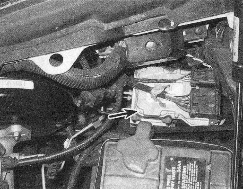
2. The ABS system has three main components – the wheel speed sensors, the anti-lock brake control module and the hydraulic control unit (see illustration). Wheel speed sensors -one at each front wheel and another located on the rear differential – send a variable voltage signal to the control unit, which monitors these signals, compares them to its program and determines whether a wheel is about to lock up. When a wheel is about to lock up, the control unit signals the hydraulic unit to reduce hydraulic pressure (or not increase it further) at that wheel’s brake caliper. Pressure modulation is handled by electrically operated solenoid valves.
2.2 The ABS hydraulic unit is mounted in the rear left corner of the engine compartment
3. If a problem develops within the system, an ABS warning light will glow on the dashboard. Sometimes, a visual inspection of the ABS system can help you locate the problem. Carefully inspect the ABS wiring harness. Pay particularly close attention to the harness and connections near each wheel. Look for signs of chafing and other damage caused by incorrectly routed wires. If a wheel sensor harness is damaged, the sensor must be replaced. Warning: Do NOT try to repair an ABS wiring harness. The ABS system is sensitive to even the smallest changes in resistance. Repairing the harness could alter resistance values and cause the system to malfunction. If the ABS wiring harness is damaged in any way, it must be replaced. Caution: Make sure the ignition is turned off before unplugging or reattaching any electrical connections.
4. If a dashboard warning light comes on and stays on while the vehicle is in operation, the ABS system requires attention. Although special electronic ABS diagnostic testing tools are necessary to properly diagnose the system, you can perform a few preliminary checks before taking the vehicle to a dealer service department.
a) Check the brake fluid level in the reservoir.
b) Verify that the computer electrical connectors are securely connected.
c) Check the electrical connectors at the hydraulic control unit.
d) Check the fuses.
e) Follow the wiring harness to each wheel and verify that all connections are secure and that the wiring is undamaged.
5. If the above preliminary checks do not rectify the problem, the vehicle should be diagnosed by a dealer service department or other qualified repair shop. Due to the complex nature of this system, all actual repair work must be done by a qualified automotive technician.
Wheel speed sensor – removal and installation
6. Loosen the wheel lug nuts, raise the vehicle and support it securely on jackstands. Remove the wheel.
7. Make sure the ignition key is turned to the Off position.
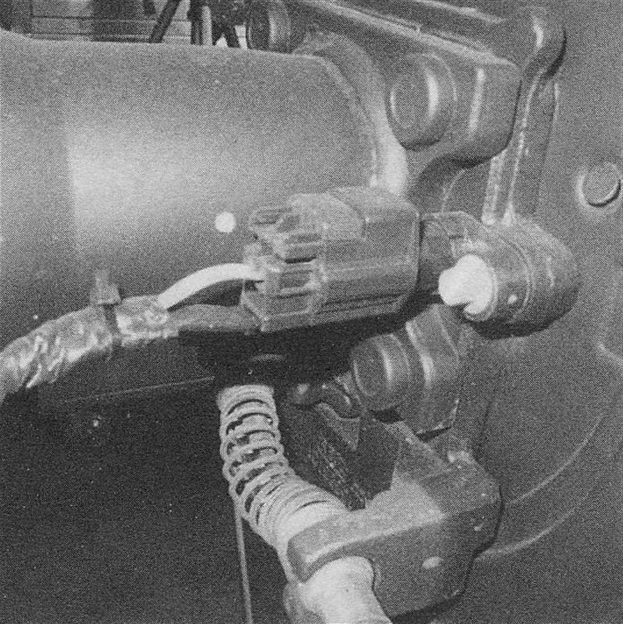
8. Trace the wiring back from the sensor, detaching all brackets and clips while noting its correct routing, then disconnect the electrical connector.
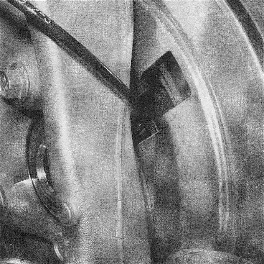
9. Remove the mounting fastener and carefully pull the sensor out from the knuckle or rear differential (see illustrations).
2.9a Front wheel speed sensor
2.9b Rear wheel speed sensor wiring connector
10. Installation is the reverse of the removal procedure. Tighten the mounting fastener securely.
11. Install the wheel and lug nuts, tightening them securely. Lower the vehicle and tighten the lug nuts to the torque listed in the Tune-up and routine maintenance Specifications.