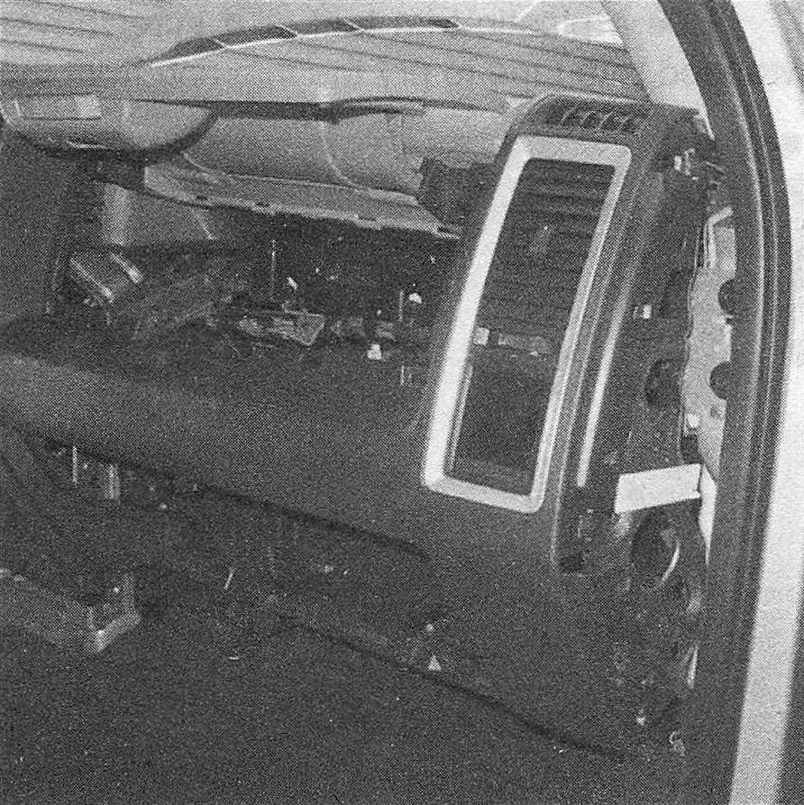
Dashboard trim panels – removal and installation
Warning: The models covered by this manual are equipped with Supplemental Restraint Systems (SRS), more commonly known as airbags. Always disable the airbag system before working in the vicinity of any airbag system component to avoid the possibility of accidental deployment of the airbags, which could cause personal injury (see Chassis electrical system).
1. Disconnect the cable (s) from the negative battery terminal(s) (see Engine electrical systems).
Instrument cluster bezel
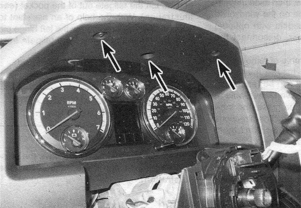
2. Remove the three screws from the top of the bezel (see illustration).
23.2 Instrument cluster bezel screws
3. Use a plastic trim tool or a screwdriver wrapped with tape to carefully release the clips around the edges of the bezel, then remove it.
4. Installation is the reverse of removal.
Center instrument panel bezel
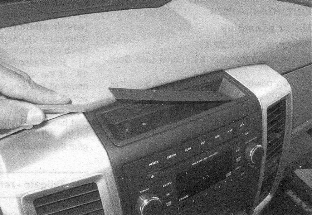
5. Use a plastic trim tool or a screwdriver wrapped with tape to carefully pry up the liners from the center trays to expose the screws under them (see illustration). Remove the two screws under each liner. Note: Some models don’t have a lower tray.
23.5 Peel up the cover to expose the screws under it
6. On column shift models with floor consoles, remove the rubber mats from the console to expose console top trim panel mounting screws and remove the screws. Raise the armrest then carefully separate the console top trim panel using a trim panel tool and remove the panel.
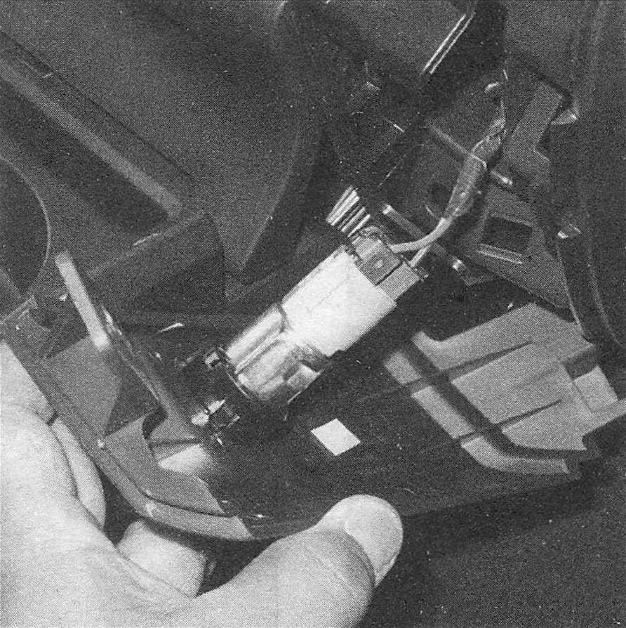
7. On early models, release the clips around the trim ring of the right-side power outlet and remove it. Then remove the screw under the power outlet trim ring, if equipped. Note: Some models have a power outlet to the left of the center trim bezel. These models don’t have a screw under them.
8. On later models, remove the retaining screw above the outlet.
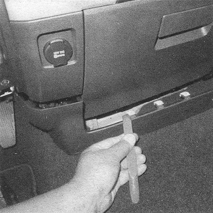
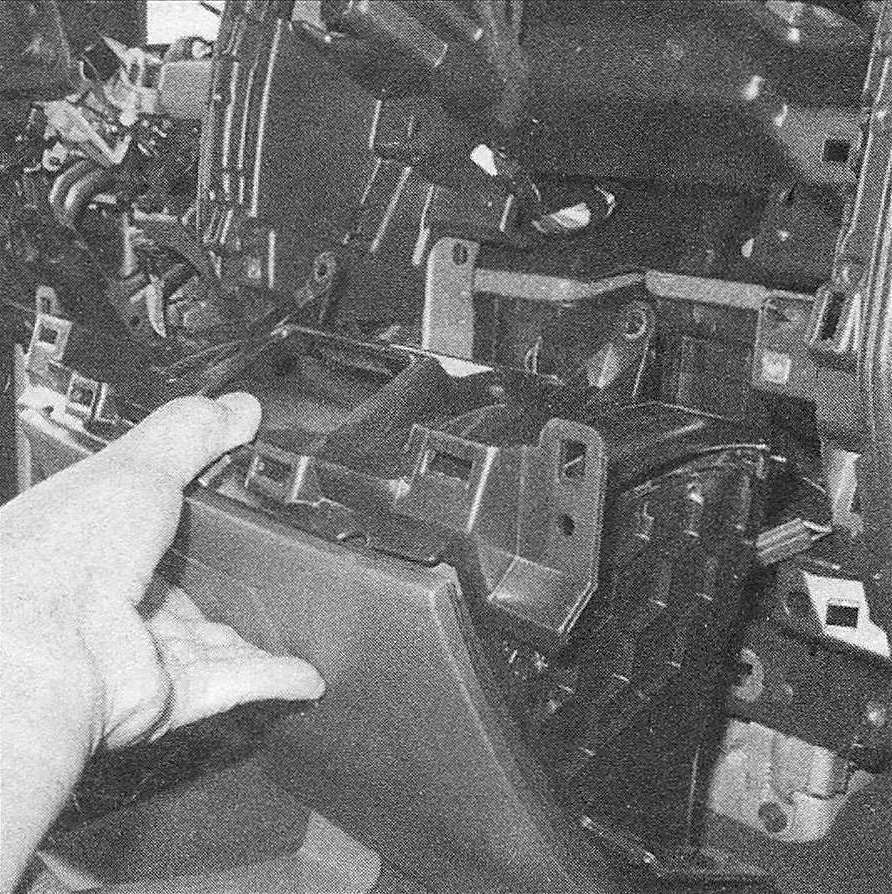
9. Using the trim tool, pry up the floor console trim ring and the shifter bezel, if so equipped. Remove the lower trim panel on vehicles without a console (see illustration). Remove the screws under the trim panel. Note: There are five screws that secure the center bezel on most models – two at the top under the tray liner, two at the bottom, and one at the center right.
23.9 On vehicles without a center console, carefully pry off this lower trim panel
10. Release the clips that secure the center instrument panel bezel and remove it using a non-scratching plastic trim tool.
11. Disconnect the wiring harnesses.
12. Installation is the reverse of removal.
Left lower instrument trim panel
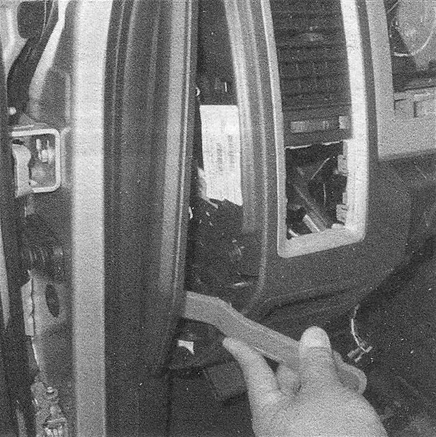
13. Use a plastic trim tool or a screwdriver wrapped with tape to pry off the cover from the left side of the instrument panel (see illus tration).
23.13 Use a plastic tool to remove the instrument panel end cap
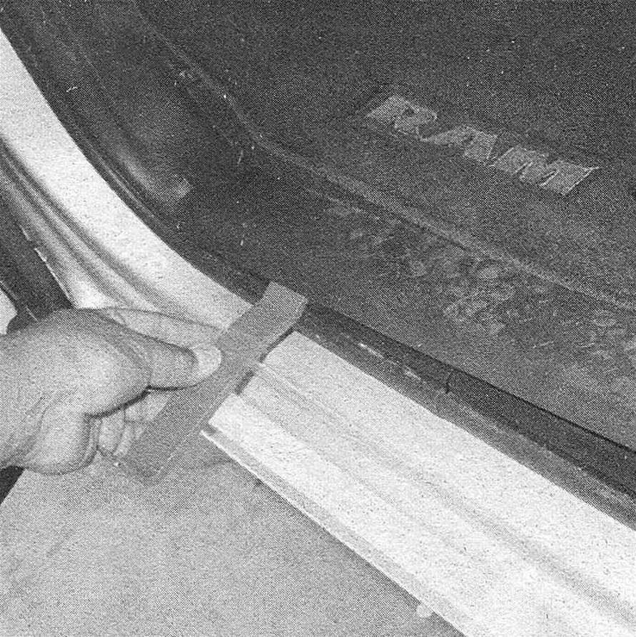
14. Remove the left threshold trim panel (see illustration).
23.14 Carefully pry upward to remove the door threshold trim strips
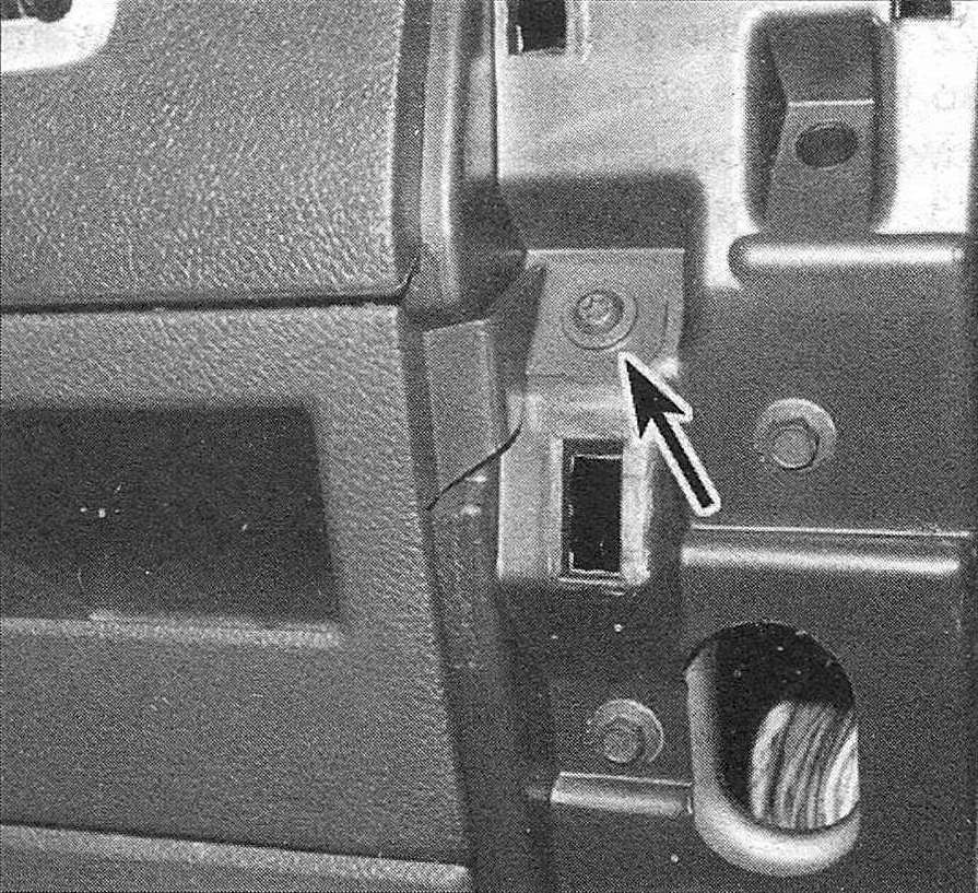
15. Remove the screws that secure the bezel to the main section of the instrument panel (see illustrations).
23.15a Two screws secure the lower left trim panel; one screw not shown can be reached with the door open
23.15b There is another screw under the parking brake release handle on some models
16. Use the plastic tool to release the clips, then tilt the top of the bezel down and disconnect any wiring harnesses. Remove the bezel by detaching it from the hooks.
17. Installation is the reverse of removal.
Headlight switch bezel
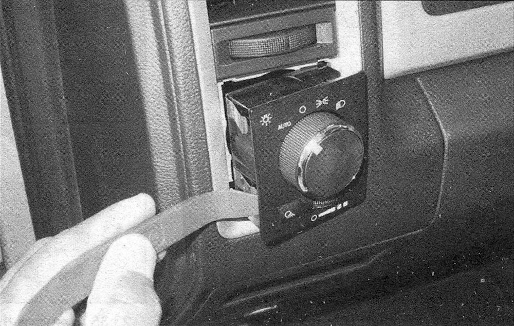
18. Use a plastic trim stick to carefully pry around the edge of the headlight switch bezel (see illustration). Note: There are two clips on each side.
23.18 The headlight switch is retained by spring clips on each side
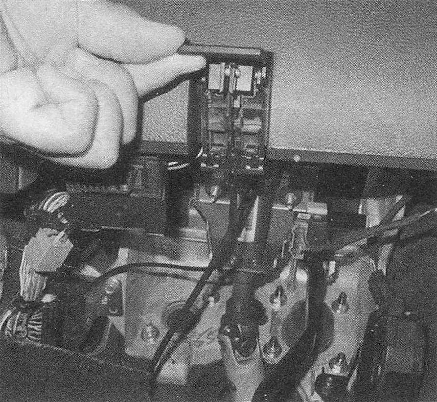
19. Pull the panel out far enough to disconnect all electrical connectors, then remove the bezel.
20. Installation is the reverse of removal.
Glove box
21. Open the glove box door.
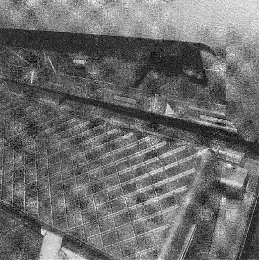
22. Push the sides of the glove box inward so the stops clear the instrument panel, then lower the door completely.
23. Pull the glove box door away from the instrument panel to detach the hinge from the instrument panel (see illustration). Remove the glove box.
23.23 The glove box can be removed from its hinges by fully opening it
24. Installation is the reverse of removal.
Storage bin
25. Remove the glove box (see Steps 20 through 22).
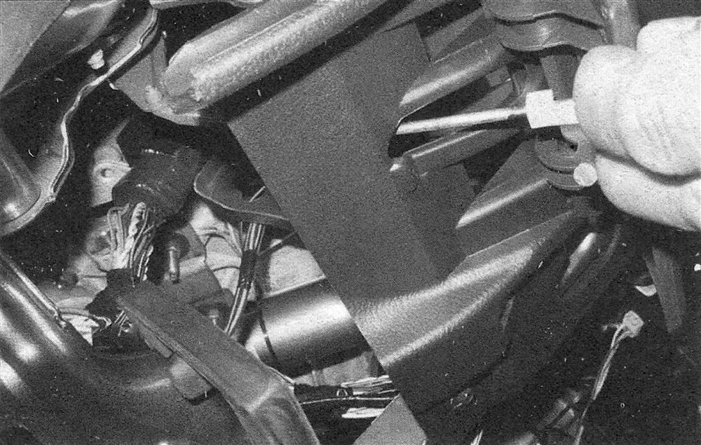
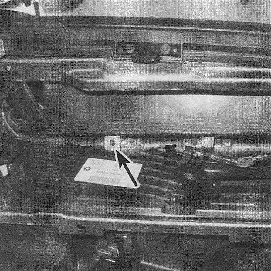
26. Working through the glove box opening, remove the screw from the rear of the storage bin (see illustration).
23.26 This screw secures the storage bin
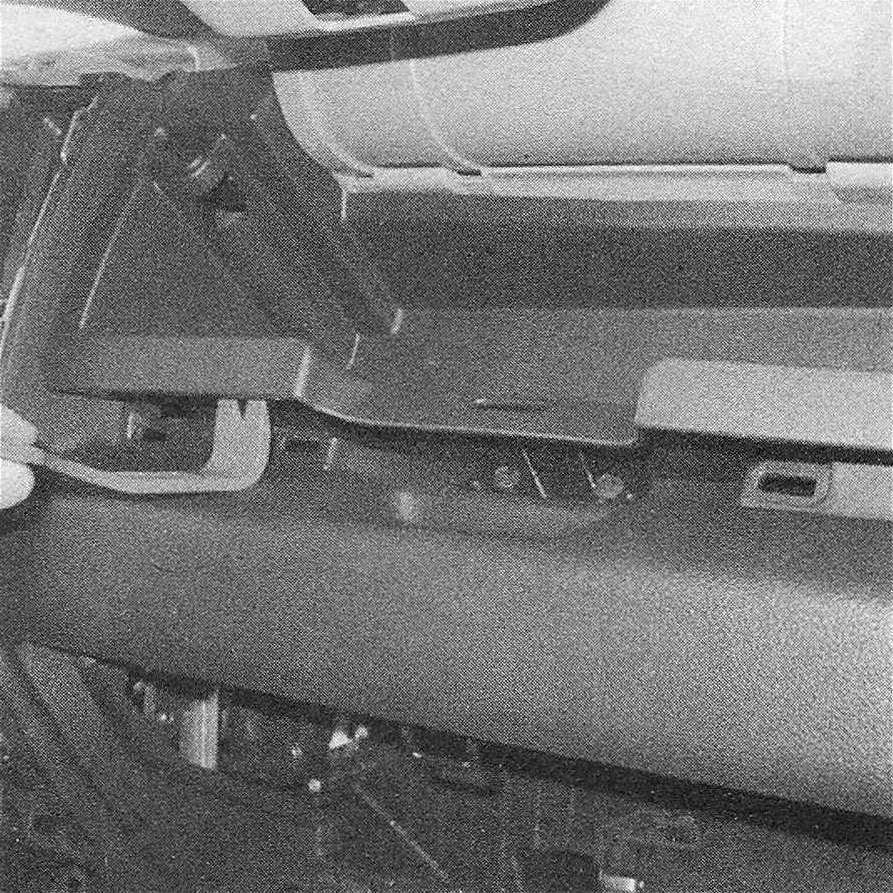
27. Open the bin door and release the clips that retain the bin (see illustration).
23.27 After removing the screw through the glove box opening, pry out the storage bin with a plastic tool
28. Pull the bin out far enough to disconnect the wiring harness, then remove it.
29. Installation is the reverse of removal.
Windshield pillar trim panels
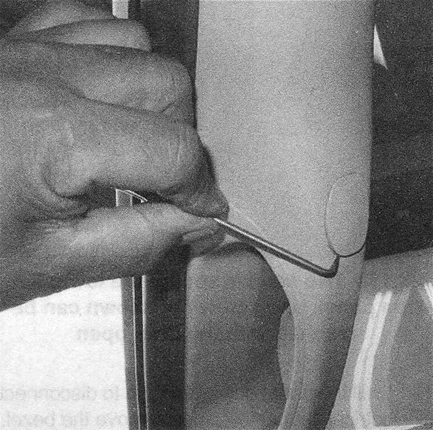
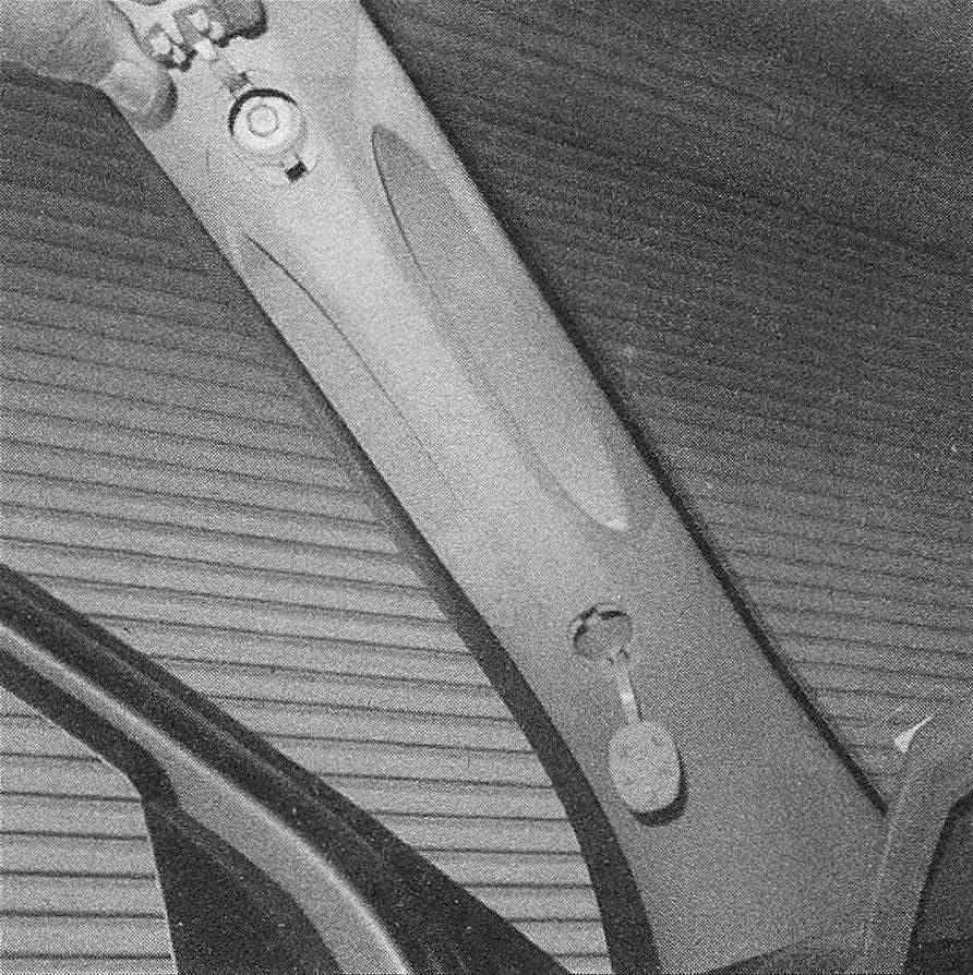
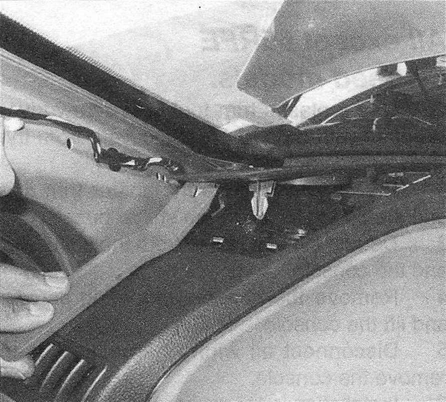
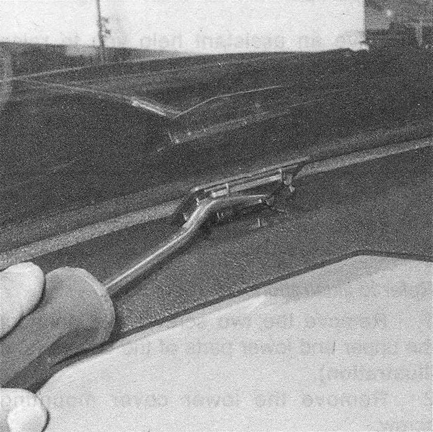
30. Use a small screwdriver to open the covers in the trim panel (see illustration). Note: There’s a notch at the bottom to insert the tool.
23.30 Use a tool with a small point to flip open the windshield trim panel bolt covers …
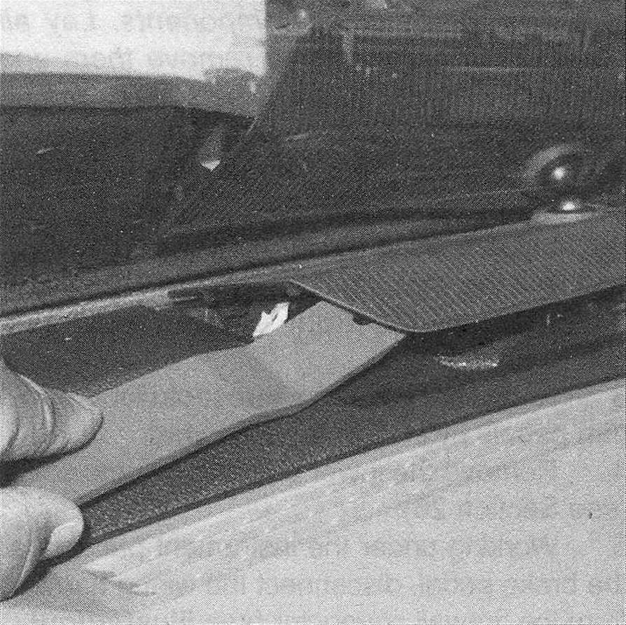
31. Remove the bolts under the covers (see illustration), then pull the cover free.
23.31 … then remove the bolts
32. Installation is the reverse of removal.
Cup holder
33. Remove the center instrument panel bezel (see Steps 5 through 11).
34. Pull off the lower trim panel (see illus tration 23.8).
35. Remove the screws from the side trim panels and remove the panels (see illustration).
23.35 Remove the screws from the top and bottom of each side trim panel and disconnect the wiring
36. Remove the cup holder (see illustration).
23.36 Remove the cup holder
37. Installation is the reverse of removal.
Driver’s knee trim panel
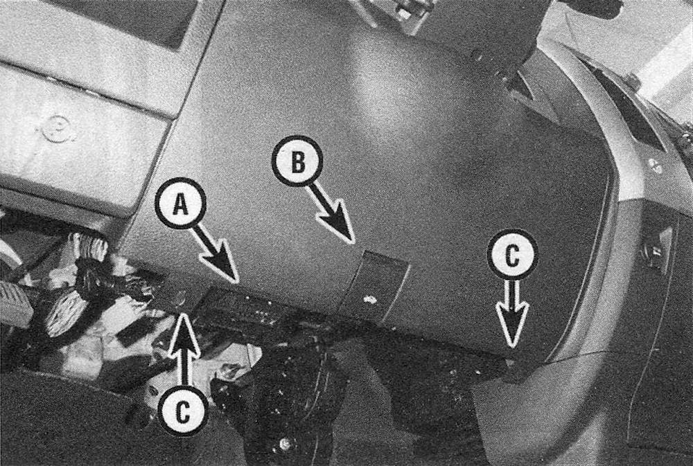
38. Carefully pry the hood release handle off of the trim panel (see illustration). Push in the tabs on the data link connector and push it through the hole in the rear of the cover.
23.38 Use a small screwdriver to release the clip that retains the hood release handle
39. Remove the two lower mounting screws (see illustration). Use a plastic trim tool or a screwdriver wrapped with tape to carefully pry the cover off, then remove the trim panel.
23.39 Data link connector (A) and hood release handle (B); the lower cover can be pried off when the screws (C) are removed
40. Installation is the reverse of removal.
Instrument panel cover
Note: This is a difficult and time-consuming procedure. If you decide to attempt it, make notes or take pictures as you go to keep track of the locations of all components. Lay all parts out in order as you remove them and label any complex assemblies so they can be installed correctly.
41. Remove the steering column covers (Steering column covers – removal and installation).
42. Remove the steering column if necessary (see Suspension and steering systems).
43. Remove the four retainers from the wireless ignition node, disconnect the wiring and remove it.
44. Remove the floor console from vehicles so equipped (Console – removal and installation).
45. Use a plastic trim tool or a screwdriver wrapped with tape to pry off the lower center trim bezel (see illustration 23.9).
46. Remove the windshield pillar trim panels (see Steps 29 and 30) and the defrost grilles (see illustration).
23.46 Pry up the defrost registers
47. Remove the covers from the bolts along the windshield line, then remove the bolts (see illustration).
23.47 There are several concealed screws along the base of the windshield
48. Remove the center instrument panel bezel (see Steps 5 through 11).
49. Remove the radio (see Chassis electrical system).
50. Remove both power outlets and their bezels.
51. Remove the instrument cluster bezel (see Steps 2 and 3), then remove the cluster (see Chassis electrical system).
52. Remove the bezel from the parking brake release handle.
53. Remove the headlight switch and the air register above it by prying both out with a plastic trim tool (see Chassis electrical system).
54. Remove the instrument panel speakers and the light sensor (see illustration).
23.54 Use a plastic trim removal tool or a screwdriver wrapped with tape to remove the light sensor as well as the speaker grilles
55. Use a plastic trim tool or a screwdriver wrapped with tape to remove the right air register (see illustration).
23.55 Remove the right air register by prying it out with a plastic tool
56. Remove the glove box (see Steps 21 through 23).
57. Remove the storage bin (see Steps 25 through 28).
58. Remove the passenger’s airbag (see Chassis electrical system).
59. Remove all of the 26 instrument panel cover screws, pull the cover rearward, then disconnect the passenger’s airbag wiring harness. Note: Count the screws to make sure they’re all accounted for. It also helps to make notes of where they belong so you don’t end up with leftover screws and a noisy instrument panel. Alternatively, a small dot of bright paint at each screw location will help with installation.
60. Remove the instrument panel cover.
61. Installation is the reverse of removal.
