Valve covers – removal and installation
Removal
1. Disconnect the cable from the negative terminal of the battery (see Engine electrical systems).
2. Remove the air filter housing, the air intake duct and the throttle body resonator (see Fuel and exhaust systems – gasoline engines).
Right (passenger’s) side cover
Warning: Wait until the engine is completely cool before beginning this procedure.
3. Drain the cooling system (see Tune-up and routine maintenance).
4. Remove the heater hoses.
5. Remove the drivebelt (see Tune-up and routine maintenance) and the air conditioning compressor (see Cooling, heating and air conditioning systems). Position the A/C compressor to the side without disconnecting the refrigerant lines from the compressor.
6. Detach the heater hoses.
7. Remove the oil filler tube.
8. Remove the rear right breather tube and filter.
9. Remove the PCV hose.
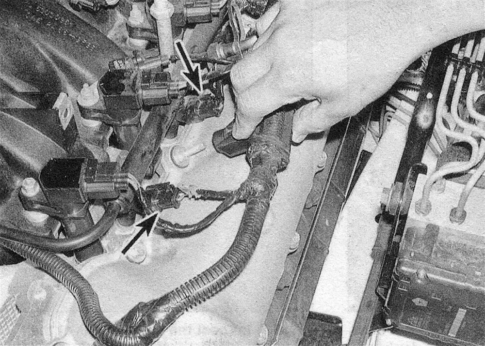
10. On V6 engines, disconnect the injector and coil wiring, then detach the wire harnesses and move them out of the way (see illustration).
5.10 Detach the wiring harness from the valve cover studs, then disconnect the fuel injector electrical connectors and position the harness aside
11. On V8 engines, remove the spark plug wires.
Left (driver’s) side cover
12. On V8 engines, remove the spark plug wires.
13. Move the injector wire harnesses to the front of the valve cover.
14. Remove the left breather tube.
Either cover
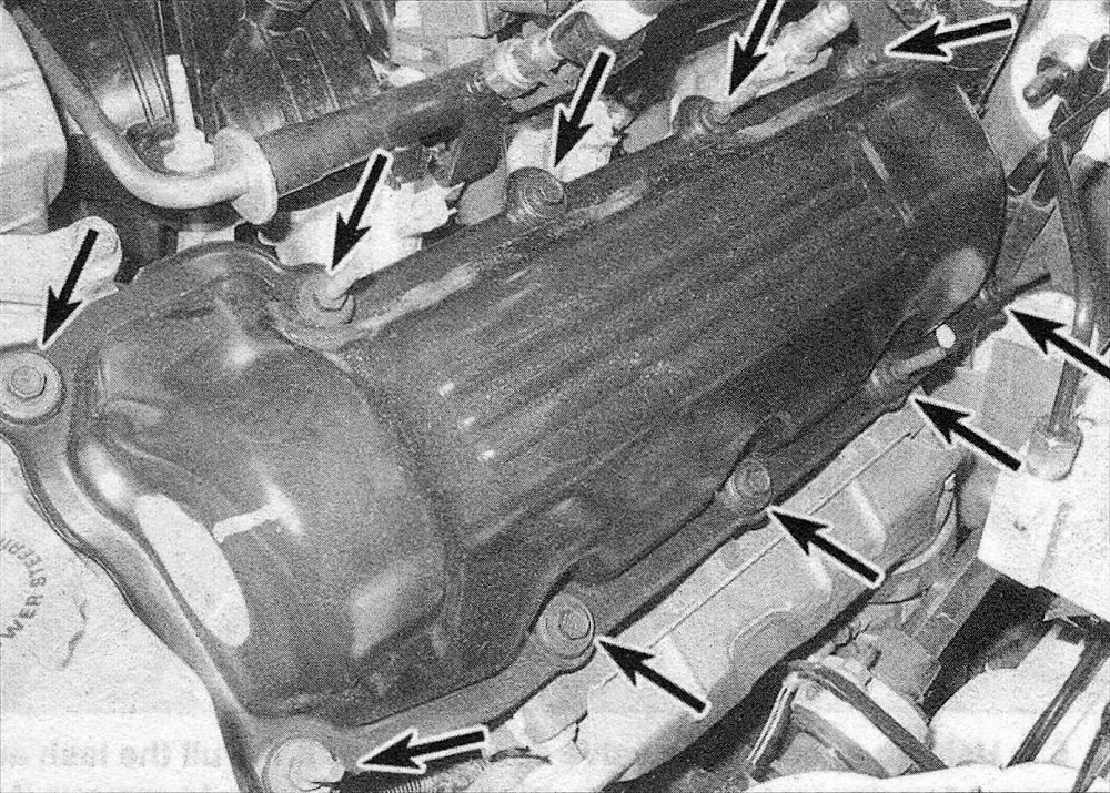
15. Remove the valve cover bolts (see illus tration). Make a note of the locations of the bolts with studs before removal to ensure correct positioning during installation.
5.15 Remove the valve cover bolts (left side shown)
16. Detach the valve cover. Note: If the cover sticks to the cylinder head, use a block of wood and a hammer to dislodge it. If the cover still won’t come loose, pry on it carefully, but don’t distort the sealing flange.
Installation
17. The mating surfaces of each cylinder head and valve cover must be perfectly clean when the covers are installed. Caution: Do not use harsh cleaners when cleaning the valve covers or damage to the covers may occur. Note: The valve cover gasket can be reused if it isn’t hardened, cracked or otherwise damaged.
18. Clean the mounting bolt or stud threads with a wire brush if necessary to remove any corrosion and restore damaged threads. Use a tap to clean the threaded holes in the heads.
19. Place the valve cover and gasket in position, then install the bolts in the correct locations from which they where removed. Tighten the bolts in several steps to the torque listed in this Chapter’s Specifications.
20. Complete the installation by reversing the removal procedure. Refill the cooling system, if drained (see Tune-up and routine maintenance). Start the engine and check carefully for oil leaks.