Timing chain and sprockets – removal, inspection and installation
Warning: Wait until the engine is completely cool before beginning this procedure.
Note: Special tools are necessary to complete this procedure. Read through the entire procedure and obtain the special tools before beginning work.
Note: These engines utilize three timing chains. The primary timing chain runs around the crankshaft sprocket and the idler gear sprocket. This chain synchronizes the crankshaft and pistons with the idler gear, while two secondary timing chains run around the rear of the idler gear and up to the camshaft sprockets to synchronize the valve timing with the crankshaft. Refer to Step 24 in this Section for the in-vehicle timing chain inspection procedure prior to timing chain removal.
Removal
Caution: The timing system is complex. Severe engine damage will occur if you make any mistakes. Do not attempt this procedure unless you are highly experienced with this type of repair. If you are at all unsure of your abilities, consult an expert. Double-check all your work and be sure everything is correct before you attempt to start the engine.
1. Disconnect the cable from the negative terminal of the battery (see Engine electrical systems).
2. Drain the cooling system (see Tune-up and routine maintenance).
3. Remove the engine cooling fan, the accessory drivebelt and the fan shroud from the engine compartment (see Cooling, heating and air conditioning systems).
4. Detach the heater hoses and the lower radiator hose from the timing chain cover and position them aside.
5. Unbolt the power steering pump and set it aside without disconnecting the fluid lines (see Suspension and steering systems).
6. Remove the alternator (see Engine electrical systems).
7. Unbolt the air conditioning compressor (if equipped) and position it aside without disconnecting the refrigerant lines.
8. Remove the accessory drivebelt tensioner from the timing chain cover (see illustration).
7.8 Drivebelt tensioner retaining bolt
9. Remove the valve covers (Valve covers – removal and installation) and the spark plugs (see Tune-up and routine maintenance). Remove all of the rocker arms (Rocker arms and hydraulic lash adjusters – removal, inspection and installation). Note: These steps are not absolutely necessary, but it will help make alignment of the camshaft sprockets easier upon installation and also eliminate any possibility of the pistons contacting the valves during this procedure, since these are interference engines.
10. Remove the Camshaft Position (CMP) sensor from the right cylinder head (see Emissions and engine control systems).
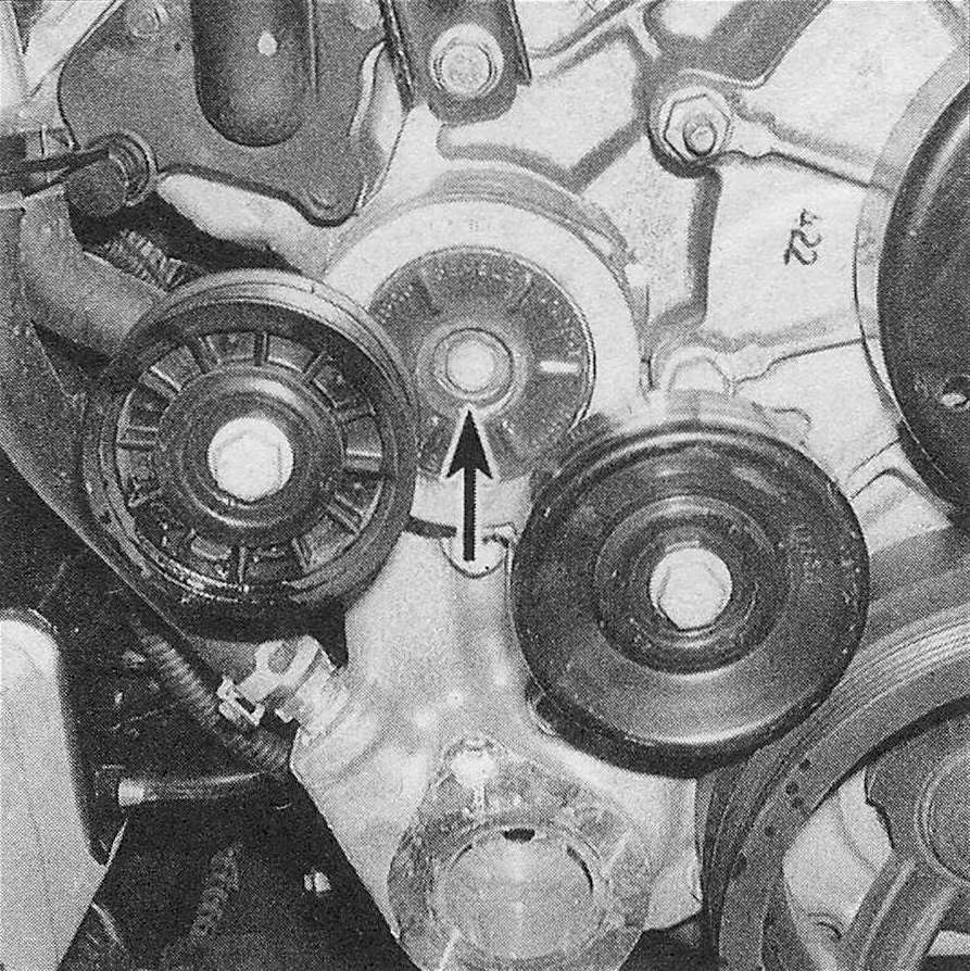
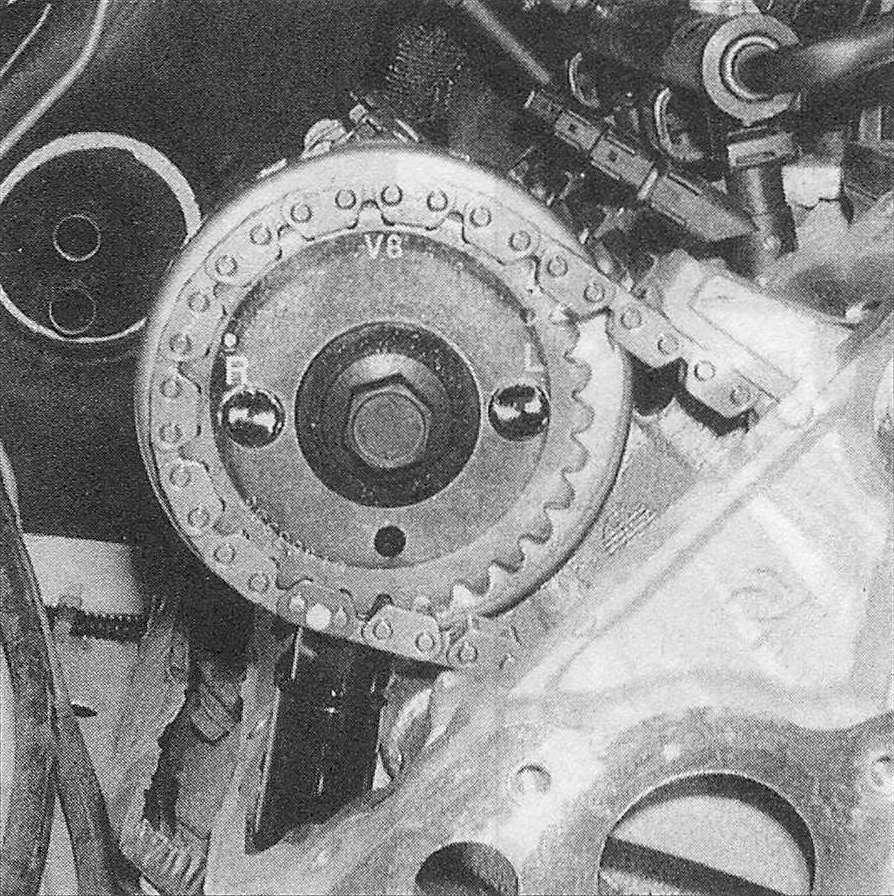
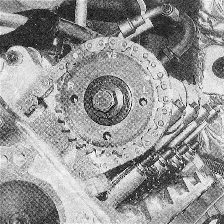
11. Position the number one piston at TDC on the exhaust stroke (one revolution from TDC on the compression stroke – Top Dead Center (TDC) for number one piston – locating). Visually confirm the engine is at TDC on the exhaust stroke, by verifying that the timing mark on the crankshaft damper is aligned with the mark on the timing chain cover and the «V6″ or «V8″ marks on the camshaft sprockets are pointing straight up in the 12 o’clock position (see illustration 4.8 and the accompanying illustration).
7.11 When the engine is at TDC on the exhaust stroke, the mark on the crankshaft damper is aligned with the mark on the timing chain cover, and the «V6″ or «V8″ marks on the camshaft sprockets should be pointing to the 12 o’clock position
12. Remove the crankshaft damper/pulley (Crankshaft pulley/vibration damper – removal and installation).
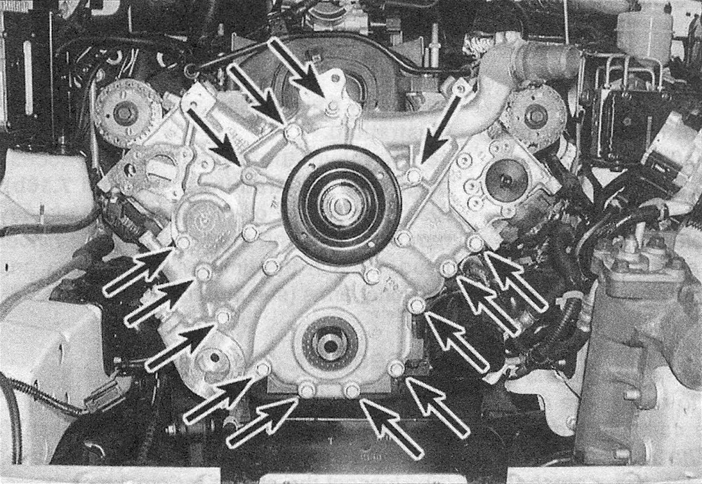
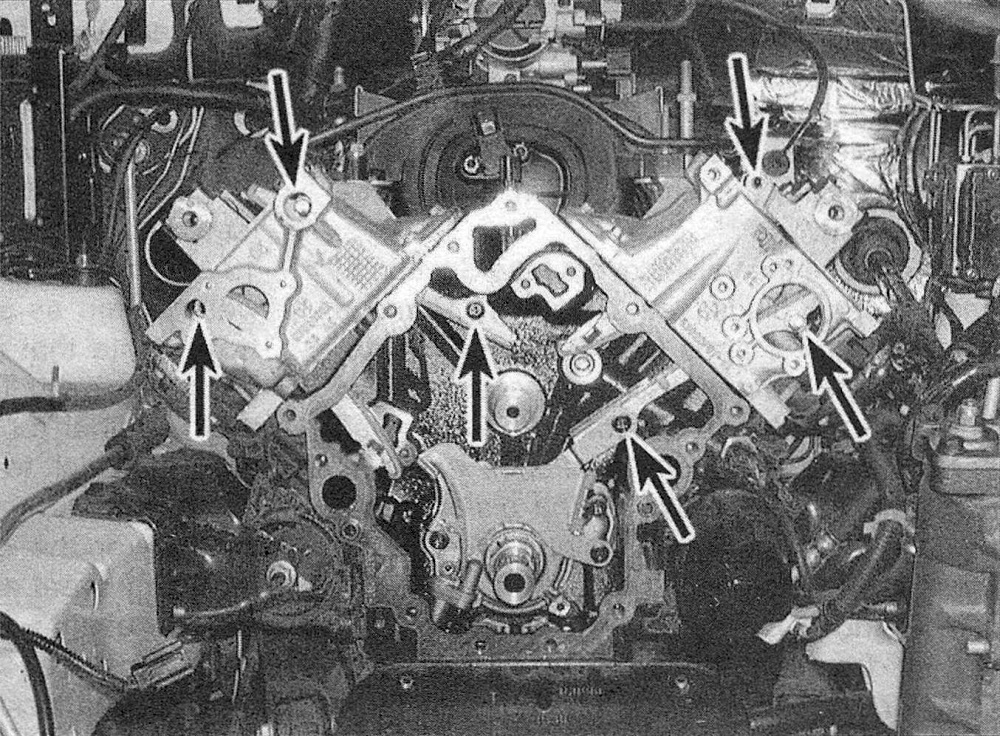
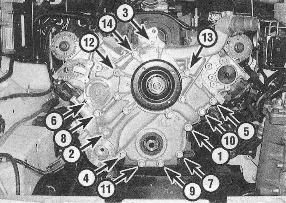
13. Remove the timing chain cover and the water pump as an assembly (see illustration). Note that various types and sizes of bolts are used. They must be reinstalled in their original locations. Mark each bolt or make a help remember where they go.
7.13 Timing chain cover retaining bolts
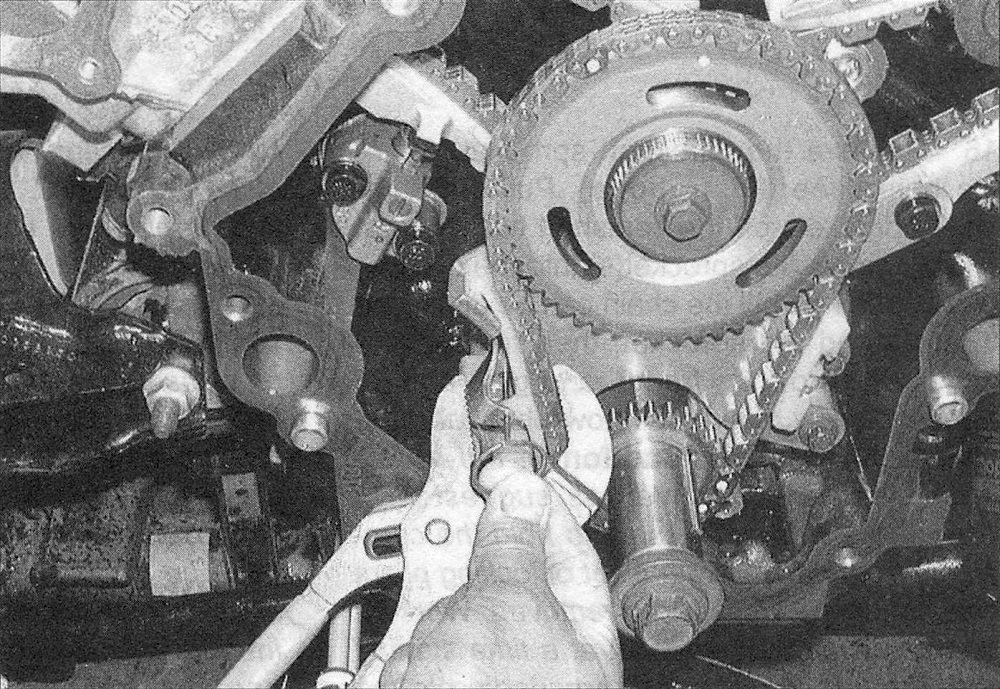
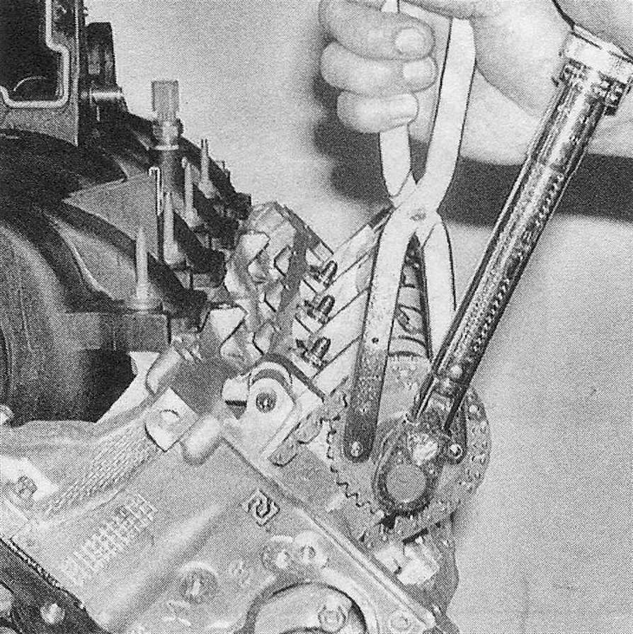
14. Cover the sketch to oil pan opening with shop rags to prevent any components from falling into the engine. Collapse the primary timing chain tensioner with a pair of locking pliers and install a locking pin into the holes in the tensioner body to keep it in the retracted position (see illustration).
7.14 Locking the primary timing chain tensioner in the retracted position
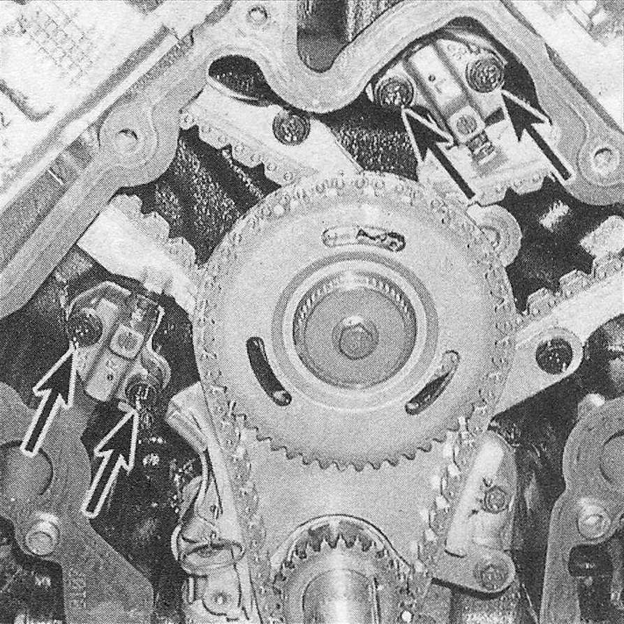
15. Remove the secondary timing chain tensioners (see illustration)
7.15 Secondary timing chain tensioner mounting bolts
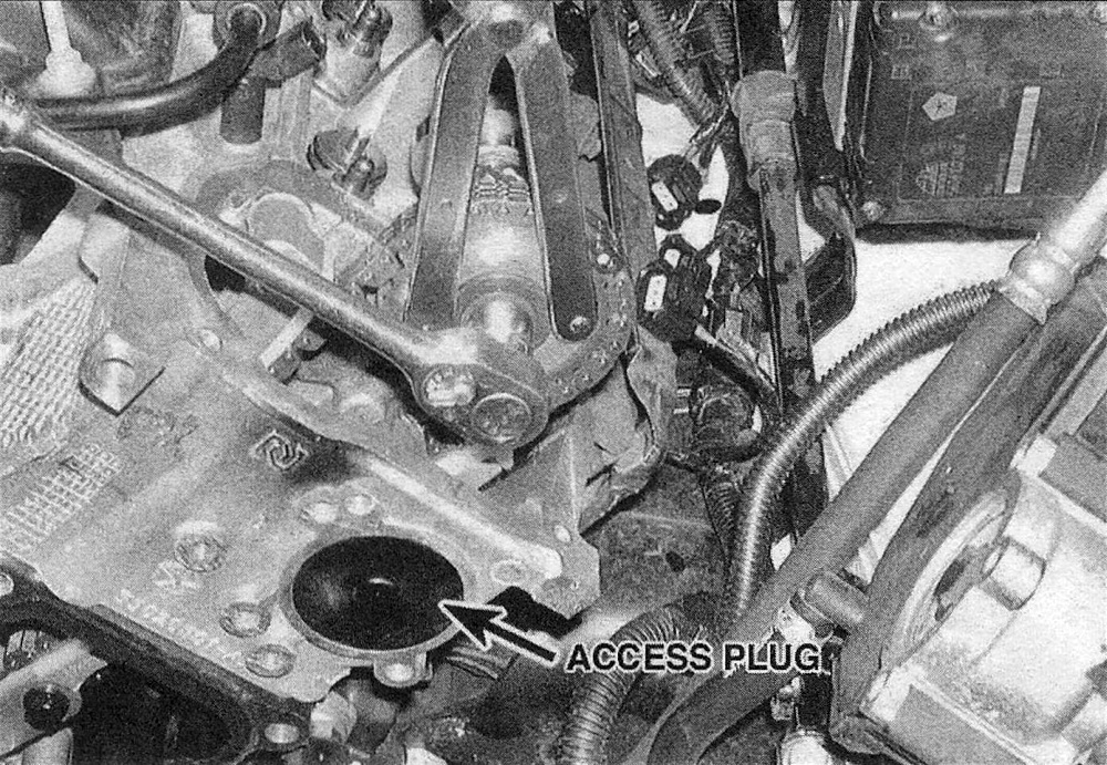
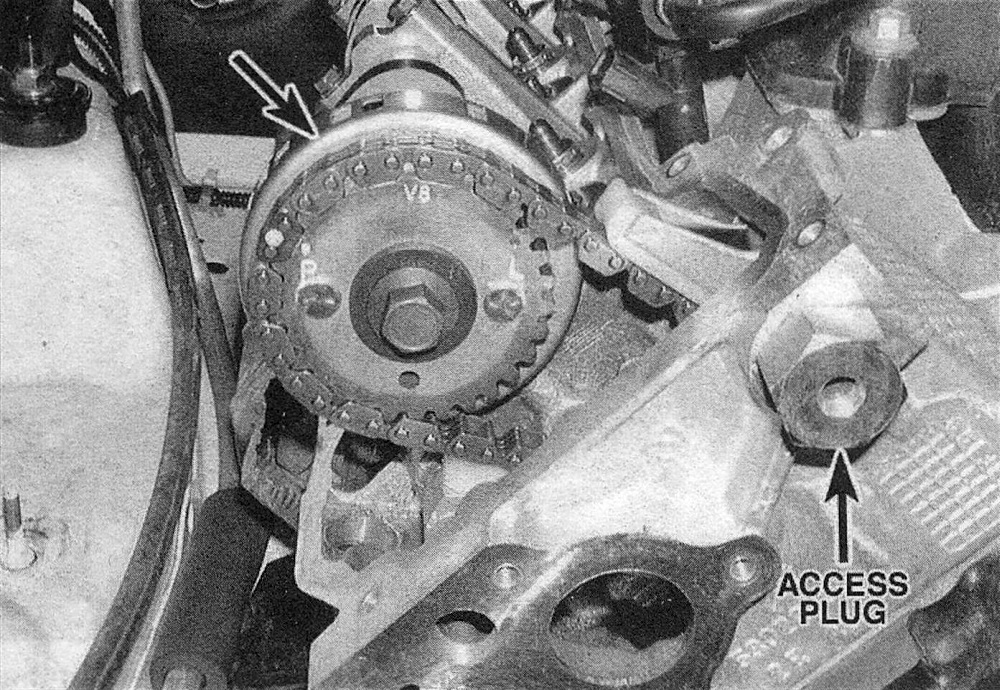
16. Remove the camshaft sprocket retaining bolts (see illustrations). Pull the camshaft sprockets off the camshaft hubs one at a time. Lower the sprocket(s) into the cylinder head opening until the chain can be displaced from around the sprocket, then remove the camshaft sprockets from the engine and let the secondary chains fall down between the timing chain guides.Caution: If the rocker arms were not removed as suggested in Step 9, it will be necessary to hold the camshafts from rotating with a set of locking pliers while the sprocket is being removed. Work on one camshaft and sprocket at a time starting with the left sprocket and proceeding to the right sprocket. After the sprocket is removed from the camshaft(s), let the camshaft slowly rotate to its neutral position. This is typically 15-degrees clockwise on the left camshaft sprocket and 45-degrees counterclockwise on the right camshaft. Force from the valve springs will make the camshafts rotate as the sprockets are removed. Sudden movement of the camshafts may allow the valves to strike the pistons. Caution: Never install the locking pliers on a camshaft lobe as damage to the camshaft will occur. When using locking pliers, always rotate the camshaft by the shaft. Caution: Do not rotate the crankshaft or camshafts separately after the secondary timing chains are loosened or removed with the rocker arms installed in the engine as piston or valve damage may occur. The only exception to this rule is when the camshafts must be rotated slightly, to realign the camshaft sprockets with the camshafts during installation. Caution: The right camshaft sprocket is identified by the camshaft position sensor ring which is fastened to the rear of the sprocket. Be extremely careful not to damage or place a magnetic object of any kind near the camshaft position sensor ring or a no start condition may occur after installation.
7.16a Remove the left camshaft sprocket bolt while holding the sprocket with a pin spanner wrench – note the chain guide access plug
7.16b The right camshaft sprocket is identified by the camshaft position sensor ring which is fastened to the rear of the sprocket - be extremely careful not to damage or place a magnetic object of any kind near the camshaft position sensor ring or a no start condition may occur after installation
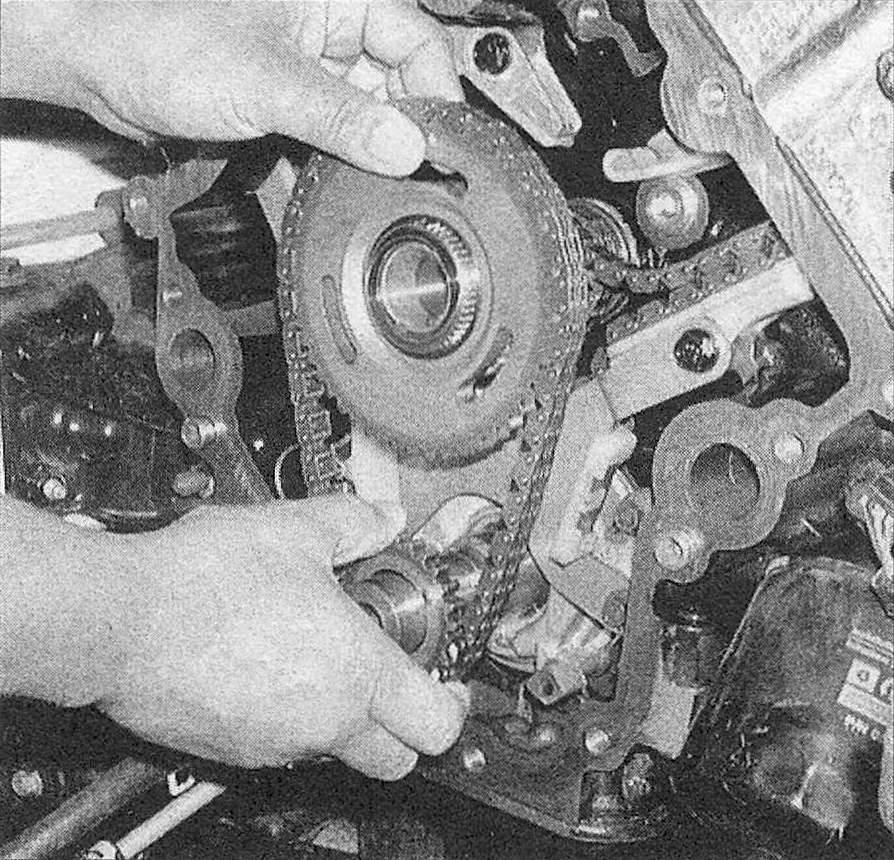
17. Remove the idler sprocket bolt, then detach the idler sprocket, the crankshaft sprocket, the primary timing chain and the secondary timing chains as an assembly (see illustration).
7.17 Remove the primary timing chain and the secondary chains from the engine as an assembly
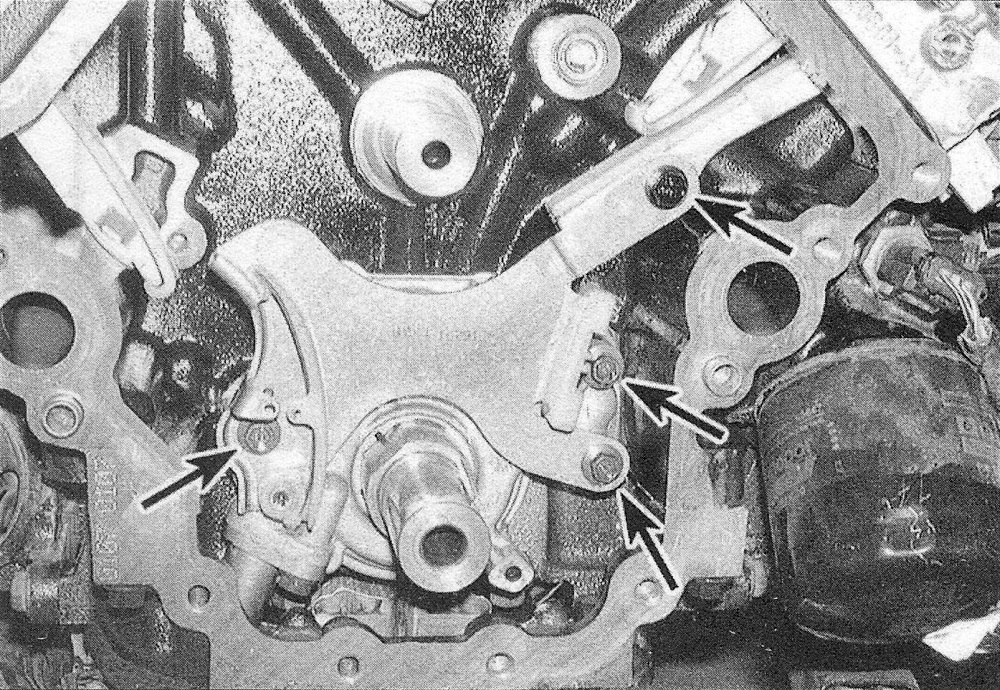
18. Remove the cylinder head access plugs (see illustrations 7.16a and 7.16b). Also remove the oil fill tube (if not already removed) from the front of the right cylinder head. Detach the timing chain guides and tensioner arms (see illustration).
7.18 Timing chain guide and tensioner arm pivot bolts
Inspection
19. Inspect the camshaft and crankshaft sprockets for wear on the teeth and keyways.
20. Inspect the chains for cracks or excessive wear of the rollers.
21. Inspect the facings of the primary chain tensioner, secondary chain guides and tensioner arms for excessive wear. If any of the components show signs of excessive wear or the chain guides are grooved in excess of 0.039 inch deep, they must be replaced.
22. If any of the timing chain guides are excessively grooved or melted, the tensioner lube jet may be clogged. Remove the jet and clean it with a small metal pick, then blow compressed air through it to remove any debris or foreign material (see illustration).
7.22 If excessive wear on the chain guides is evident, check the oil jet on the side of each secondary tensioner for clogging
23. Inspect the idler sprocket bushing, shaft and spline joint for wear.
24. Inspect the tensioner piston and ratchet assembly on both of the secondary chain tensioners. If it appears there has been heavy contact between the piston, and ratchet assembly, replace the tensioner arm and secondary timing chain. Note: Secondary timing chain stretch can be checked by rotating the engine clockwise until the pistons in the secondary tensioners reach their maximum travel or extension. Using a machinist’s ruler or a dial caliper, measure the piston protrusion or extension from the stepped ledge on the piston to the tensioner housing on each tensioner. If the maximum extension of either tensioner piston exceeds 0.590 inch, the secondary timing chains are worn beyond their limits and should be replaced.
Installation
Caution: Before starting the engine, carefully rotate the crankshaft by hand through at least two full revolutions (use a socket and breaker bar on the crankshaft pulley center bolt). If you feel any resistance, STOP! There is something wrong – most likely, valves are contacting the pistons. You must find the problem before proceeding. Check your work and see if any updated repair information is available.
25. If removed, install the timing chain guides and tensioner pivot arms back onto the engine and tighten the bolts to the torque listed in this Chapter’s Specifications. Apply several drops of medium strength thread-locking compound to the tensioner pivot arm bolts before installing them. Note that the silver bolts retain the guides to the cylinder head and the black colored bolts retain the guides to the engine block.
26. If the primary timing chain tensioner was removed or replaced, install it back onto the engine in the locked position and tighten the lower two bolts to the torque listed in this Chapter’s Specifications (see illustration).
7.26 Primary timing chain tensioner/oil pump mounting bolts ensioner for clogging
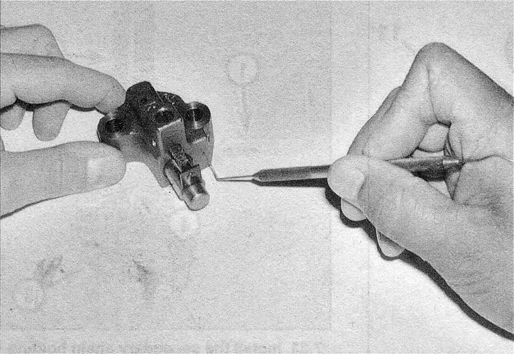
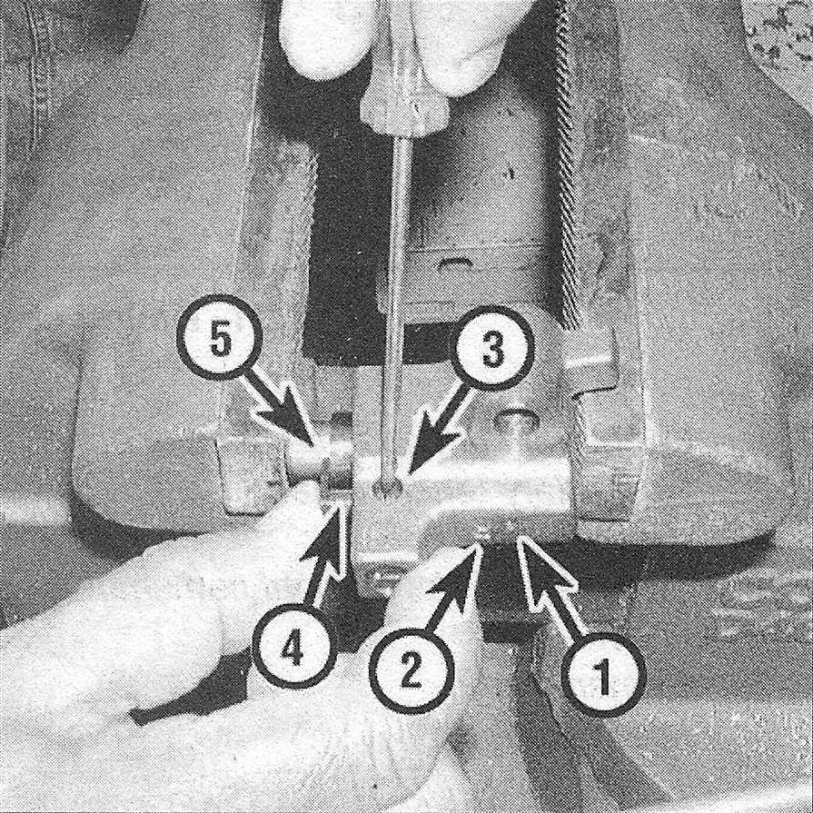
27. Working on one secondary timing chain tensioner at a time, compress the tensioner piston in a vise until the stepped edge is flush with the tensioner body (see illustration). Insert a small scribe or other suitable tool into the side of the tensioner body and push the spring loaded ratchet pawl away from the ratchet mechanism, then push the ratchet down into the tensioner body until it’s approximately 0.080 inch away from the tensioner body. Insert the end of a paper clip into the hole on the front of the tensioner to lock the tensioner in place.
7.27 Locking the secondary tensioner (s) in the retracted position – note the identification mark on the side of the tensioner, as they are not interchangeable
1 Insert locking pin
2 Identification mark
3 Ratchet pawl
4 Ratchet
5 Tensioner piston
28. After the two secondary tensioners have been compressed and locked into place, install them on the engine and tighten the bolts to the torque listed in this Chapter’s Specifications. Make sure the tensioner with the «R» mark is installed on the right secondary chain (passenger’s side) and the tensioner with «L» mark is installed on the left secondary chain (driver’s side). The secondary chain tensioners cannot be switched with one another. Also make sure the plate behind the left secondary chain tensioner is installed correctly.
29. If you purchased a new timing chain, verify that you have the correct timing chain for your vehicle by counting the number of links the chain has and comparing the new chain with the old chain. Also compare the position of the colored links in the new chain with the position of the colored links in the old chain.
30. Note that the idler sprocket has three sprockets and a gear incorporated into it. The front or forward facing sprocket (the largest of the three) is for the primary timing chain, the second or middle sprocket is for the left secondary chain, the third or rear sprocket is for the right secondary chain and the gear (3.7L V6 engines only) is for the counterbalance shaft (4.7L V8 engines don’t have a counterbalance shaft). The next five Steps will involve assembling the timing chains onto the idler sprocket on a workbench.
31. Place the idler sprocket on a workbench with the mark on the front in the 12 o’clock position. Loop the right camshaft chain over the rear gear (farthest away from the primary chain gear) on the idler sprocket and position it so that the two plated links on the chain are visible through the lower (4 o’clock) window in the idler sprocket (see illustration).
7.31 Timing chain installation details
1 Secondary timing chain tensioner
2 Secondary tensioner arm
3 Chain guide
4 Two plated links on right camshaft chain
5 Primary chain
6 Idler sprocket
7 Crankshaft sprocket
8 Primary chain tensioner
9 Two plated links on left camshaft chain
10 Right camshaft sprocket and secondary chain
11 Left camshaft sprocket and secondary chain
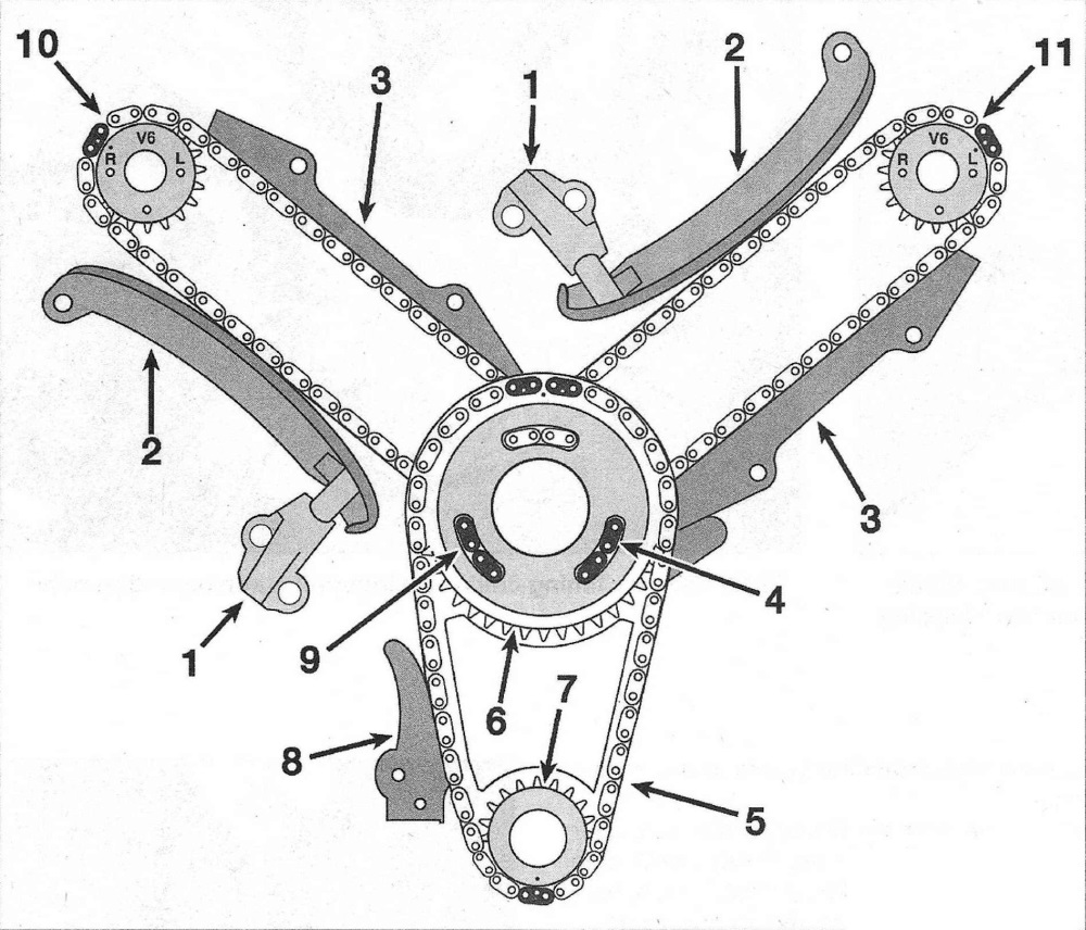
32. Loop the left camshaft chain over the front of the idler sprocket and position it over the middle gear so that the two plated links on the chain are visible through the lower (8 o’clock) window in the idler sprocket. Note: After the left chain is in position, the two plated links on the right chain will no longer be visible through the 4 o’clock window in the idler sprocket, so be sure that the right camshaft chain is installed correctly before installing the left camshaft chain.
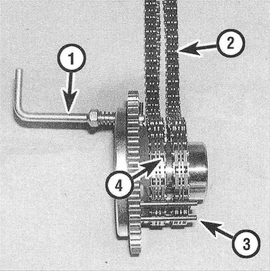
33. After the secondary (camshaft) chains have been installed properly on the idler sprocket, install the special secondary chain holding tool onto the idler sprocket (see illus tration). This tool serves as a third hand, to secure the camshaft chains to the idler sprocket during the installation of the idler sprocket onto the engine.
7.33 Install the secondary chain holding tool onto the idler sprocket with the plated links on the right camshaft chain in the 4 o’clock position and the left camshaft chain in the 8 o’clock position (typical)
1 Secondary chain holding tool
2. Right camshaft timing chain
3. Secondary chain holding tool retaining pins
4. Left camshaft timing chain
34. Install the primary timing chain onto the primary chain gear of the idler sprocket and align the double plated links with the mark on the front of the sprocket. The mark on the idler sprocket should still be in the 12 o’clock position.
35. Insert the teeth of the crankshaft sprocket into the primary timing chain with the mark on the crankshaft sprocket pointing down in the 6 o’clock position and aligned with the single plated link on the chain.
36. Lubricate the idler shaft and bushing with clean engine oil.
37. Install the idler sprocket, the crankshaft sprocket and the timing chains with the chain holding tool as an assembly onto the engine. Slide the crankshaft sprocket over the keyway on the crankshaft and position the idler sprocket partially over the idler shaft (just enough to hold the primary chain in place). Then feed the secondary chains up through the chain guides and the cylinder head. Note: It may be easier to bend a hook in the end of a coat hanger to help pull the secondary chains up through the timing chain guides and the cylinder head opening.
38. Loop the secondary chains over the camshaft hubs and secure them with rubber bands to remove the slack from the chains.
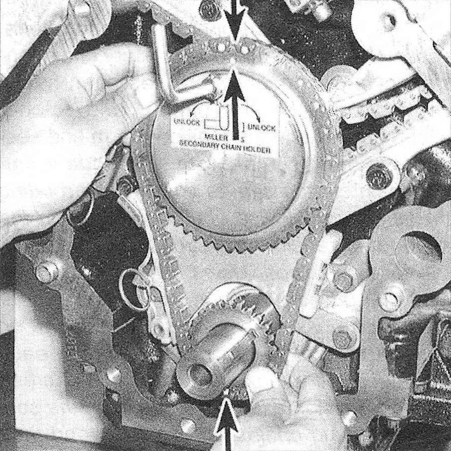
39. Push the idler sprocket, primary timing chain and the crankshaft sprocket assembly back on to the engine until they’re fully seated (see illustration). On 3.7L V6 engines, the timing mark on the idler sprocket gear must align with the timing mark on the counterbalance shaft gear while doing this. Note: On 3.7L V6 engines, make sure the single mark on the counterbalance shaft gear is positioned between the two marks on the idler sprocket gear.
7.39 Align the timing mark on the idler procket gear with the timing mark on the counterbalance shaft, then install the idler sprocket, the crankshaft sprocket, the timing chains and the chain holding tool as an assembly onto the engine with the marks aligned as shown – feed the secondary chains up through the timing chain guides and loop them over the camshaft hubs, then push the primary chain assembly the rest of the way until it’s seated
40. Thoroughly clean the idler sprocket bolt. Make sure all oil is removed from the bolt threads before installation, as over-tightening of bolts may occur if oil is not removed, then lubricate the idler sprocket washer with small amount of clean engine oil making sure not to get oil on the bolt threads. Remove the secondary timing chain holding tool from the idler sprocket, then install the idler sprocket retaining bolt and tighten it to the torque listed in this Chapter’s Specifications.
41. Align the «L» mark on left camshaft sprocket with the plated link on the left camshaft chain and position the camshaft sprocket over the camshaft hub (see illustration 7.31). The camshaft may have to be rotated slightly to align the dowel pin on the camshaft with the slot on the sprocket.
42. Align the «R» mark on right camshaft sprocket with the plated link on the right camshaft chain and position the camshaft sprocket over the camshaft hub. The camshaft may have to be rotated slightly to align the dowel pin on the camshaft with the slot on the sprocket. Note: If the rocker arms were not removed as suggested in Step 9, it will be necessary to rotate and hold the camshafts with a set of locking pliers while the sprocket is being installed. This is typically 15-degrees counterclockwise on the left camshaft sprocket and 45-degrees clockwise on the right camshaft (the exact opposite of removal). Work on one camshaft and sprocket at a time starting with the left sprocket and proceeding to the right sprocket and never rotate the camshaft by a camshaft lobe or damage to the camshaft will occur
43. Thoroughly clean the camshaft sprocket bolts. Make sure all oil is removed from the bolt threads before installation, as over-tightening of bolts may occur if oil is not removed, then lubricate the bolt washers with small amount of clean engine oil making sure not to get oil on the threads.
44. Install the camshaft sprocket bolts finger tight.
45. Verify that all the plated timing chain links are aligned with their corresponding marks (see illustration 7.31).
46. Remove the locking pins from the primary timing chain tensioner and the secondary timing chain tensioners. Caution: Do not manually extend the tensioners; doing so will only over-extend the tensioners and lead to premature timing chain wear
47. Rotate the engine two complete revolutions and re-verify the position of the timing marks again. The idler sprocket mark should be located in the 12 o’clock position and the crankshaft sprocket mark should be located in the 6 o’clock position with the «V6″ or «V8″ marks on the camshaft sprockets located in the 12 o’clock position.
48. Using a spanner wrench to hold the sprockets from turning, tighten the camshaft sprocket bolts to the torque listed in this Chapter’s Specifications (see illustration).
7.48 Tightening the left camshaftsprocket bolt
49. Remove all traces of old sealant or gasket material from the timing chain cover and the engine block.
50. Place the timing chain cover and gasket in position on the engine and install the bolts in their original locations and tighten the bolts to the torque listed in this Chapter’s Specifications. Follow the correct tightening sequence (see illustration).
7.50 Timing chain cover tightening sequence
51. The remainder of installation is the reverse of removal. Use pipe sealant on the cylinder head plugs to prevent oil leaks.
52. Change the engine oil and filter and refill the cooling system (see Tune-up and routine maintenance).