Rocker arms and hydraulic lash adjusters – removal, inspection and installation
Note: A special valve spring compressor available from most aftermarket specialty tool manufacturers will be required for this procedure. The only other alternative to accomplishing this task without the use of this special tool is to remove the timing chains and the camshafts, which requires major disassembly of the engine and surrounding components. Note: This engine is a non-freewheeling (interference) engine and the pistons must be down in the cylinder bore before the valve and spring assembly can be compressed to allow rocker arm removal.
1. Before beginning this procedure, place the transmission in Park and apply the parking brake or block the rear wheels. Also, disable the ignition system by disconnecting the primary electrical connectors at the ignition coils and removing the spark plugs (see Tune-up and routine maintenance).
2. Remove the valve cover (s) (Valve covers – removal and installation).
3. Before the rocker arms and lash adjusters are removed, arrange to label and store them, so they can be kept separate and reinstalled on the same valve they were removed from.
4. Rotate the engine with a socket and ratchet in a clockwise direction by the crankshaft pulley/vibration damper bolt until the piston (s) are positioned correctly to remove the rocker arms from the corresponding cylinders as follows. Start the sequence from TDC number 1 on the compression stroke (Top Dead Center (TDC) for number one piston – locating).
On V6 engines:
a) With the No.1 piston at TDC on the compression stroke, remove the rocker arms from cylinders No. 2 and 6.
b) Rotate the crankshaft another 180-degrees (1/2-turn) from TDC on the compression stroke to bring the No. 1 piston to BDC on the firing stroke. Remove the rocker arms from cylinder No. 1 with the No. 1 piston at Bottom Dead Center (BDC) on the firing stroke.
c) Rotate the crankshaft another 180-degrees (1/2-turn) from BDC on the firing stroke to bring the No.1 piston to TDC on the exhaust stroke. Remove the rocker arms from cylinders No. 3 and 5 with the No. 1 piston at TDC on the exhaust stroke.
d) Rotate the crankshaft another 180-degrees (1/2-turn) from TDC on the exhaust stroke to bring the No.1 piston to BDC on the intake stroke. Remove the rocker arms from cylinder No. 4 with the No. 1 piston at BDC on the intake stroke.
On V8 engines:
a) With the No.1 piston at TDC on the compression stroke, remove the rocker arms from cylinders No. 2 and 8.
b) Rotate the crankshaft another 360-degrees (1-turn) from TDC on the compression stroke to bring the No.1 piston to TDC on the exhaust stroke. Remove the rocker arms from cylinders No. 3 and 5 with the No. 1 piston at TDC on the exhaust stroke.
c) Position cylinder No. 3 at TDC on the compression stroke. Remove the rocker arms from cylinder No. 4 and 6.
d) Position cylinder No. 2 at TDC on the compression stroke. Remove the rocker arms from cylinder No. 1 and 7.
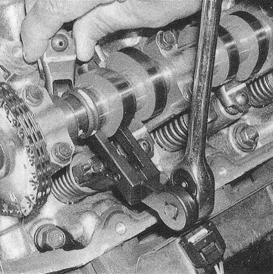
5. Hook the valve spring compressor around the base of the camshaft. Depress the valve spring just enough to release tension on the rocker arm to be removed. Once tension on the rocker arm is relieved, the rocker arm can be removed by simply pulling it out (see illustration).
6.5 Using a special type valve spring compressor, depress the valve spring just enough to remove the rocker arm
6. If you’re removing or replacing only a few of the rocker arms or lash adjusters, locate the cylinder number of the rocker arm or lash adjuster you wish to remove in Step 4, then rotate the crankshaft to the corresponding position. Remember to keep the rocker arm and lash adjuster for each valve together so they can be reinstalled in the same locations. Refer to Section Top Dead Center (TDC) for number one piston – locating as necessary to help position the designated cylinder at TDC.
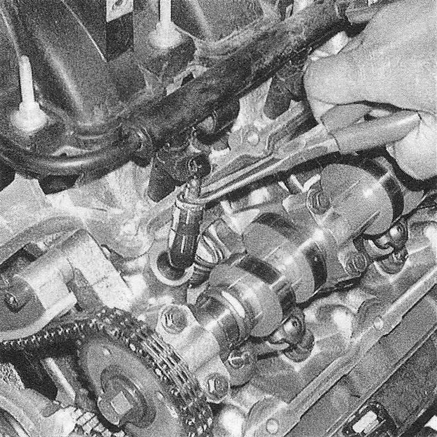
7. Once the rocker arms are removed, the lash adjusters can be pulled out of the cylinder head and stored with the corresponding rocker arm (see illustration).
6.7 Pull the lash adjuster up and out of its bore to remove it from the cylinder head
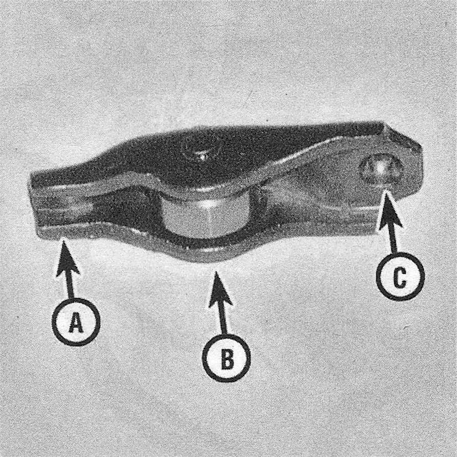
8. Inspect each rocker arm for wear, cracks and other damage. Make sure the rollers turn freely and show no signs of wear, also check the pivot area for wear, cracks and galling (see illustration).
6.8 Inspect the rocker arms at the following locations
A. Valve stem seat
B. Roller
C. Lash adjuster pocket
9. Inspect the lash adjuster contact surfaces for wear or damage. Make sure the lash adjusters move up and down freely in their bores on the cylinder head without excessive side-to-side play.
10. Installation is the reverse of removal with the following exceptions: Always install the lash adjuster first and make sure they’re at least partially full of oil before installation. This is indicated by little or no lash adjuster plunger travel.