Intake manifold – removal and installation
Warning: The engine must be completely cool before beginning this procedure.
Removal
1. Relieve the fuel pressure (see Fuel and exhaust systems – gasoline engines).
2. Disconnect the cable from the negative terminal of the battery (see Engine electrical systems).
3. Remove the air intake duct from the throttle body (see Fuel and exhaust systems – gasoline engines).
4. Label and disconnect the vacuum hoses leading to the intake manifold for the PCV valve, power brake booster, cruise control servo (if used) and evaporative emission control system.
5. Disconnect all of the electrical connectors leading to the intake manifold for the various sensors, the ignition coils and the Idle Air Control (IAC) motor (if used).
6. Disconnect the electrical connectors for the alternator and the air conditioning compressor.
7. Unbolt the ground straps attached to the intake manifold and the throttle body.
8. Remove the upper dipstick tube mounting bolt.
9. On early models, detach the throttle cable and the cruise control cable from the throttle body and the throttle cable bracket. Remove the throttle body (see Fuel and exhaust systems – gasoline engines).
10. Remove the ignition coils (see Engine electrical systems).
11. Remove the fuel rails, then remove the throttle body and mounting bracket (see Fuel and exhaust systems – gasoline engines).
12. Drain some coolant from the cooling system (see Tune-up and routine maintenance), then remove the heater hoses from the front cover and heater core tubes.
13. On V8 engines, remove the coolant temperature sensor (see Emissions and engine control systems). This step is necessary to allow clearance for the intake manifold as it is removed.
14. Remove the intake manifold mounting fasteners in the reverse order of the tightening sequence (see illustration 9.20a or 9.20b).
15. The manifold will probably be stuck to the cylinder heads and force may be required to break the gasket seal. Caution: Don’t pry between the manifold and the heads or damage to the gasket sealing surfaces may occur, leading to vacuum or coolant leaks.
16. Label and detach any remaining hoses or wiring that would interfere with the removal of the intake manifold.
17. Lift the manifold up level with the vehicle and remove it from the engine.
Installation
18. Clean and inspect the intake manifoldto-cylinder head sealing surfaces. Inspect the gaskets on the manifold for tears or cracks, replacing them if necessary. The gaskets can be reused if not damaged.
19. Position the manifold on the engine, making sure the gaskets and manifold are aligned correctly over the cylinder heads, then install the intake manifold bolts hand tight.
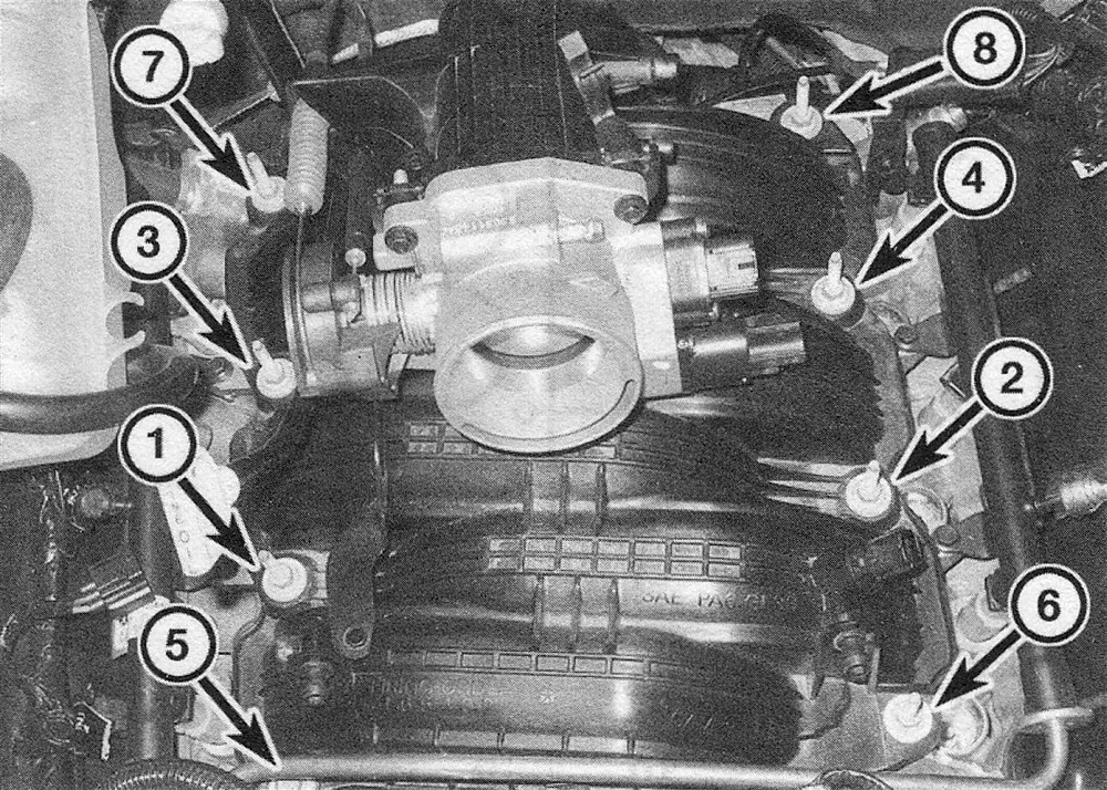
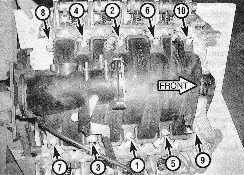
20. Following the recommended tightening sequence, tighten the bolts to the torque listed in this Chapter’s Specifications (see illustrations).
9.20a Intake manifold bolt tightening sequence – 3.7L V6
9.20b Intake manifold bolt tightening sequence – 4.7L V8
21. The remainder of installation is the reverse of removal.
22. Fill the cooling system, run the engine and check for fuel, vacuum and coolant leaks.