Camshafts – removal, inspection and installation
Note: Special tools are necessary to complete this procedure. Read through the entire procedure and obtain the special tools before beginning work.
Note: The camshafts should always be thoroughly inspected before installation and camshaft endplay should always be checked prior to camshaft removal (see Step 17).
Removal
1. Disconnect the cable from the negative terminal of the battery (see Engine electrical systems).
2. Remove the valve covers (Valve covers – removal and installation).
3. Rotate the engine with a socket and ratchet (in a clockwise direction only) by the crankshaft pulley/vibration damper bolt until the «V6″ or «V8″ marks on the camshaft sprockets are located in the 12 o’clock position (see illustration 7.11).
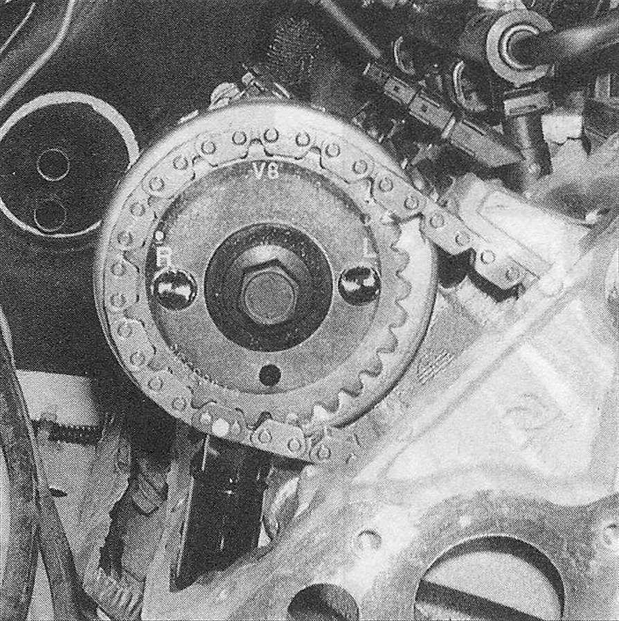
4. Using a permanent marker, apply alignment marks to the secondary timing chain links on either side of the «V6″ or «V8″ marks on both camshaft sprockets to help aid the installation process (4 marks total).
5. Using a spanner wrench to hold the camshaft sprockets from turning, loosen the camshaft sprocket bolts several turns, then retighten the bolts by hand until they’re snug up against the sprocket. If the camshaft sprockets have rotated during the bolt-loosening process, rotate the engine clockwise until the «V6″ or «V8″ marks on the cam sprockets are realigned in the 12 o’clock position.
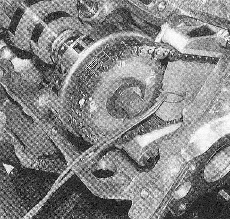
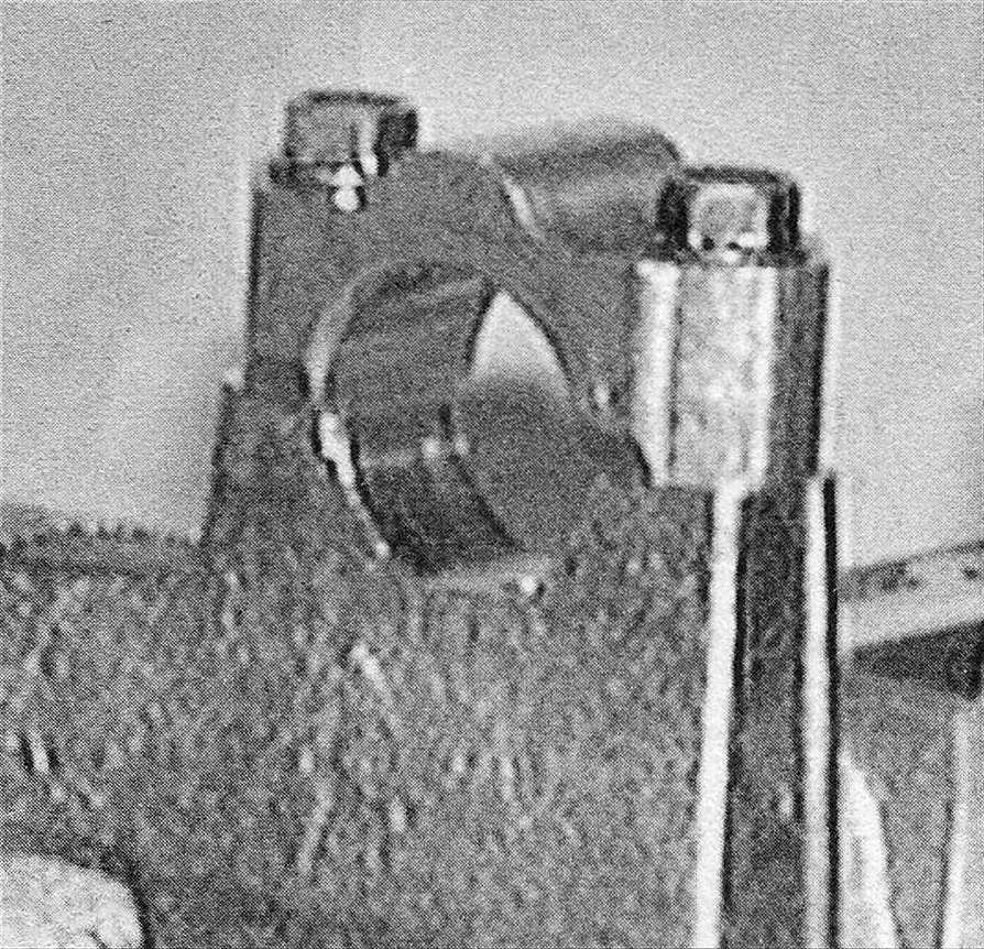
6. Install a timing chain tensioner wedge through the opening in the top of the cylinder head and force the wedge down between the narrowest section of the secondary chain (see illustration). If both camshafts are to removed, two timing chain wedges will be necessary (one for the left camshaft chain and one for the right camshaft chain). The wedge is used to secure the chain and the secondary tensioner in place while the camshaft is removed. Caution: Failure to use a timing chain wedge will allow the secondary tensioner to over-extend and require removal of the timing chain cover to reset the tensioners. Caution: Never force the wedge past the narrowest section of the secondary timing chain as damage to the tensioner will occur. If a timing chain wedge is not available, they may be fabricated using a block of wood that is 3/8 to 1/2-inch thick and a piece of wire to pull the wedge out of the cylinder head after installation.
8.6 The timing chain tensioner wedge is pushed down between the chain strands to secure the secondary chain and the tensioner in place while the camshaft is removed – this wedge is fabricated from a block of wood and a piece of wire
7. Remove the Camshaft Position (CMP) sensor (see Emissions and engine control systems).
8. Remove the camshaft sprocket retaining bolt (s) and detach the camshaft sprocket(s) from the camshaft hub(s). Disengage the camshaft chain(s) from the sprocket(s) and remove the camshaft sprocket(s) from the engine.
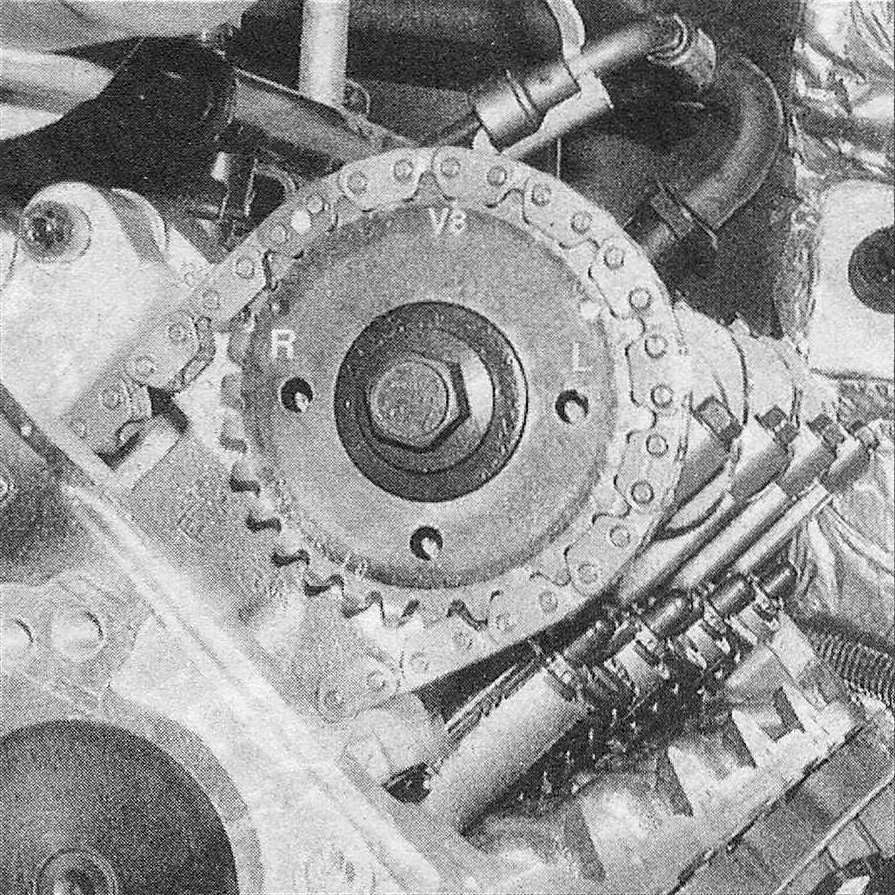
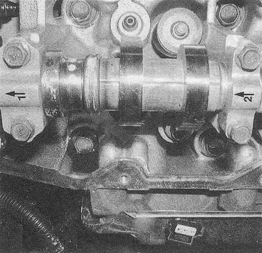
9. Make note of the markings on the camshaft bearing caps. The caps are marked from 1 to 4 or 5 with arrow marks on the caps indicating the front of the engine (see illustration). If both camshafts are being removed, use a permanent marker to mark each bearing cap on the right cylinder head with an «R» and each bearing cap on the left cylinder head with an «L» to indicate from which cylinder head they came from. Loosen the camshaft bearing caps bolts a little at a time beginning with the bearing caps on the ends, then working inward. Caution: Keep the caps in order. They must go back in the same location they were removed from.
8.9 Verify that the camshaft bearing caps are marked to ensure correct reinstallation - do not mix-up the caps from the left cylinder head with the caps from the right cylinder head
10. Detach the bearing caps. Note: The rocker arms may slide out of position. Mark the rocker arms so that they will be installed in the same location.
11. Remove the camshaft (s) from the cylinder head. Mark the camshaft(s) «Left» or «Right» to indicate which cylinder head it came from.
Inspection
12. Inspect the camshaft sprockets for wear on the teeth.
13. Inspect the chains for cracks or excessive wear of the rollers. If any of the components show signs of excessive wear they must be replaced.
14. Visually check the camshaft bearing surfaces on the cylinder head (s) for pitting, score marks, galling and abnormal wear. If the bearing surfaces are damaged, the cylinder head may have to be replaced (see illustration).
8.14 Inspect the cam bearing surfaces in each cylinder head for pits, score marks and abnormal wear – if wear or damage is noted, the cylinder head must be replaced
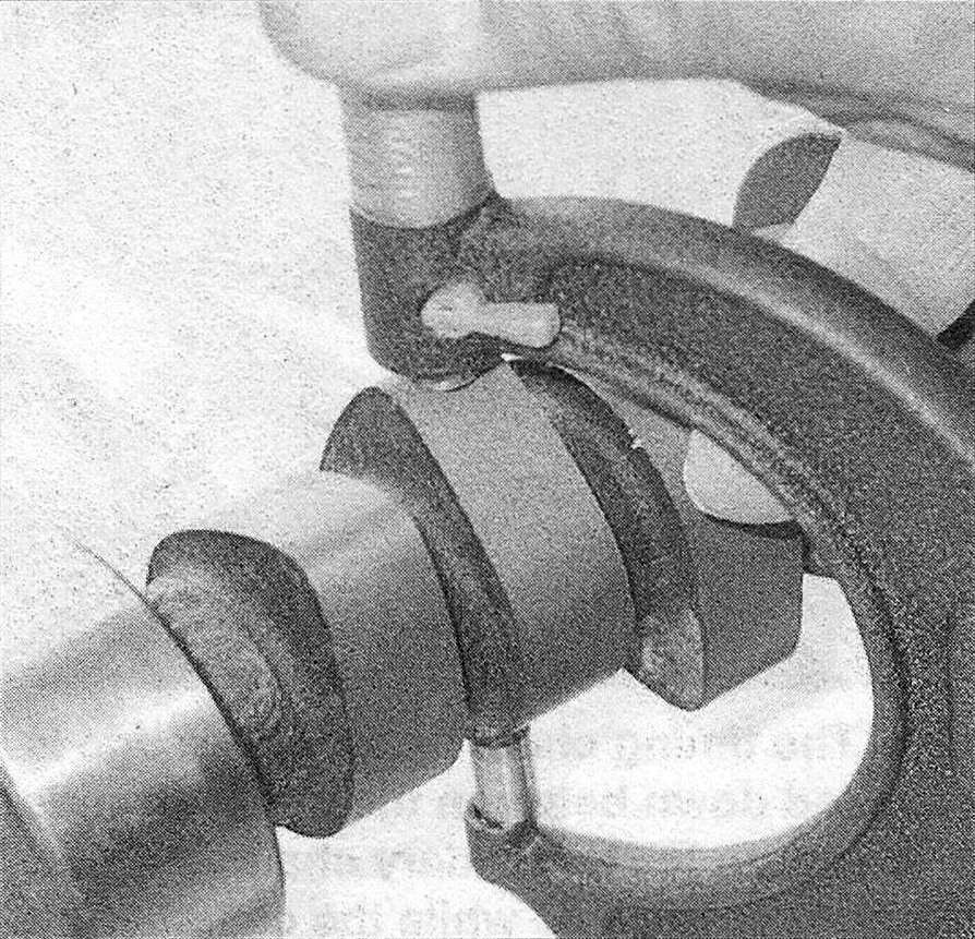
15. Measure the outside diameter of each camshaft bearing journal and record your measurements (see illustration). Compare them to the journal outside diameter specified in this Chapter, then measure the inside diameter of each corresponding camshaft bearing and record the measurements. Subtract each cam journal outside diameter from its respective cam bearing bore inside diameter to determine the oil clearance for each bearing. Compare the results to the specified journalto-bearing clearance. If any of the measurements fall outside the standard specified wear limits in this Chapter, either the camshaft or the cylinder head, or both, must be replaced.
8.15 Measure the outside diameter of each camshaft journal and the inside diameter of each bearing to determine the oil clearance measurement
16. Check camshaft runout by placing the camshaft back into the cylinder head and set up a dial indicator on the center journal. Zero the dial indicator. Turn the camshaft slowly and note the dial indicator readings. Runout should not exceed 0.0010 inch. If the measured runout exceeds the specified runout, replace the camshaft.
17. Check the camshaft endplay by placing a dial indicator with the stem in line with the camshaft and touching the snout. Push the camshaft all the way to the rear and zero the dial indicator. Next, pry the camshaft to the front as far as possible and check the reading on the dial indicator. The distance it moves is the endplay. If it’s greater than the Specifications listed in this Chapter, check the bearing caps for wear. If the bearing caps are worn, the cylinder head must be replaced.
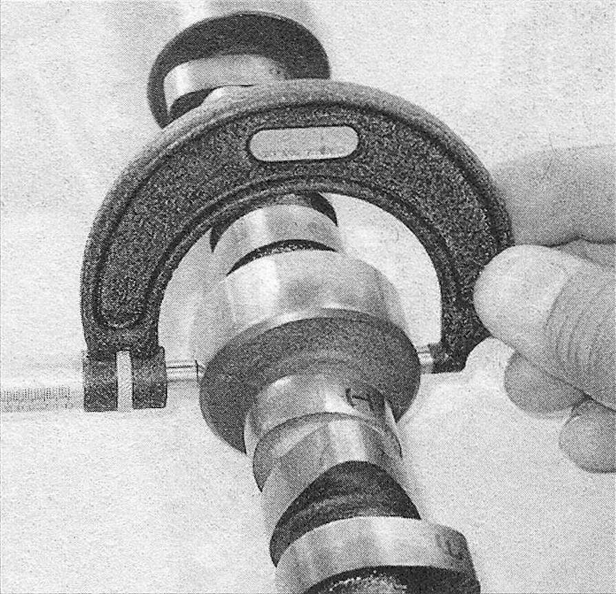
18. Compare the camshaft lobe height by measuring each lobe with a micrometer (see illustration). Measure each of the intake lobes and write the measurements and relative positions down on a piece of paper. Then measure of each of the exhaust lobes and record the measurements and relative positions also. This will let you compare all of the intake lobes to one another and all of the exhaust lobes to one another. If the difference between the lobes exceeds 0.005 inch the camshaft should be replaced. Do not compare intake lobe heights to exhaust lobe heights, as lobe lift may be different. Only compare intake lobes to intake lobes and exhaust lobes to exhaust lobes for this comparison.
8.18 Measuring cam lobe height with a micrometer, make sure you move the micrometer to get the highest reading (top of cam lobe)
Installation
19. Apply moly-based engine assembly lubricant to the camshaft lobes and journals and install the camshaft (s) into the cylinder head with the dowel pins in the 10 o’clock position. If the old camshafts are being used, make sure they’re installed in the exact location from which they came.
20. Install the bearing caps and bolts and tighten them hand tight.
21. Tighten the bearing cap bolts a little at a time, to the torque listed in this Chapter’s Specifications, starting with the middle bolts and working outward.
22. Engage the camshaft sprocket teeth with the camshaft drive chain links so that the «V6″ or «V8″ mark on the sprocket (s) is between the two marks made in Step 5 during removal, then position the sprocket over the dowel on the camshaft hub. At this point the chain marks and the «V6″ or «V8″ marks on the sprocket should be pointing up in the 12 o’clock position.
23. Thoroughly clean the camshaft sprocket bolts. Make sure all oil is removed from the bolt threads before installation, as over-tightening of bolts may occur if oil is not removed, then lubricate the bolt washers with small amount of clean engine oil making sure not to get oil on the threads.
24. Install the camshaft sprocket bolts and tighten them to the torque listed in this Chapter’s Specifications (see illustration 7.48).
25. Remove the timing chain wedge (s).
26. Install the CMP sensor (see Emissions and engine control systems)
27. Install the valve covers (Valve covers – removal and installation).
28. Connect the cable to the negative terminal of the battery.