Valve covers – removal and installation
Removal
1. Disconnect the negative battery cable from the remote ground terminal (see Engine electrical systems).
2. Remove the engine cover.
3. Remove the upper intake manifold (Intake manifolds – removal and installation).
Note: Cover open ports on the intake to prevent debris from entering the engine.
Caution: Once the valve covers are removed, the magnetic timing wheels are exposed (see illustration 9.9). The magnetic timing wheels on the camshafts must not come in contact with any type of magnet or magnetic field. If contact is made, the timing wheels will have to be replaced.
4. Remove insulator from the left valve cover by lifting the insulator up and off of the retaining posts, then remove it from the front valve cover.
5. Before removing the variable valve timing solenoid connectors from the front of each valve cover, mark them appropriately so they can be reinstalled in their original locations.
6. Disconnect the wiring harness retainers from the valve cover and move the harnesses out of the way.
7. Remove the ignition coils on both sides of the engine (see Engine electrical systems).
8. Mark the Camshaft Position (CMP) sensors to each valve cover so they can be reinstalled in their original locations, then remove the sensor(s) (see Emissions and engine control systems).
9. Remove the PCV valve from the rear cover (see Tune-up and routine maintenance).
10. Remove the bolts for the transmission dipstick tube and engine oil dipstick tube.
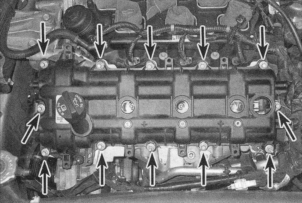
11. Remove the valve cover fasteners (see illustration) and remove the cover(s). Caution: If the cover is stuck to the cylinder head, tap one end with a block of wood and a hammer to jar it loose. If that doesn’t work, slip a flexible putty knife between the cylinder head and cover to break the gasket seal. Don’t pry at the cover-to-cylinder head joint or damage to the sealing surfaces may occur (leading to future oil leaks).
4.11 Left side valve cover mounting bolts
12. Remove and discard the valve cover gasket, then remove the spark plug tube seals.
Note: The cover gaskets can be reused if they are not damaged.
Installation
13. The mating surfaces of each cylinder head and valve cover must be perfectly clean when the covers are installed. Use a gasket scraper to remove all traces of sealant and old gasket material, then clean the mating surfaces with brake system cleaner. If there’s sealant or oil on the mating surfaces when the cover is installed, oil leaks may develop.
14. Inspect the spark plug tube seals; if damaged, carefully remove the seals using an appropriate pry tool. Position the new seal with the part number facing the valve cover, then use a socket that contacts the outer edge to drive the seal in place.
15. Apply a dab of RTV sealant at the joints where the timing chain cover meets the cylinder head.
16. Install the valve cover and bolts, then tighten the bolts to the torque listed in this Chapter’s Specifications.
17. The remainder of installation is the reverse of removal.