Oil pump – removal, inspection and installation
Removal
1. Disconnect the cable from the negative terminal of the battery (see Engine electrical systems).
2. Raise the front of the vehicle and support it securely on jackstands. Apply the parking brake and block the rear wheels to keep it from rolling off the stands.
3. Drain the engine oil (see Tune-up and routine maintenance).
4. Remove the skid plate, if equipped, and the lower splash shield fasteners then remove the splash shield.
5. Remove the lower and upper oil pans (Oil pans – removal and installation).
6. Remove the oil pump pick-up tube fastener, and remove the tube from the pump. Discard the pick-up tube 0-ring.
7. Disconnect the oil pump solenoid electrical connector from the side of the engine.
8. Working from the side of the block, depress the oil pump solenoid electrical connector locking tab and push the connector into the block.
Note: The connector will have to be maneuvered around the tensioner mounting bolt.
9. Remove the oil pump timing gear splash shield bolts and remove the splash shield.
10. Press the oil pump chain tensioner away from the chain until a 3 mm Allen wrench can be inserted into the housing to hold the tensioner back.
11. Using a permanent marker or paint, make reference marks on the chain and oil pump gear.
12. Hold the oil pump gear from moving, then remove the T45 Torx mounting bolt and the oil pump gear.
13. Hold the tensioner and remove the Allen wrench, allowing the tensioner to release. Remove the spring from the dowel pin and slide the tensioner from the oil pump.
14. Remove the oil pump mounting bolts and remove the pump.
Inspection
Note: The oil pump is not serviceable; if there is a problem, the pump assembly must be replaced.
15. Clean all parts thoroughly in solvent and carefully inspect the rotors, pump cover, and timing chain cover for nicks, scratches, or burrs. Replace the assembly if it is damaged.
16. Use a straightedge and a feeler gauge to measure the oil pump cover for warpage (see illustration). If it’s warped more than the limit listed in this Chapter’s Specifications, the pump should be replaced.
12.16 Place a straightedge across the oil pump cover and check it for warpage with a feeler gauge

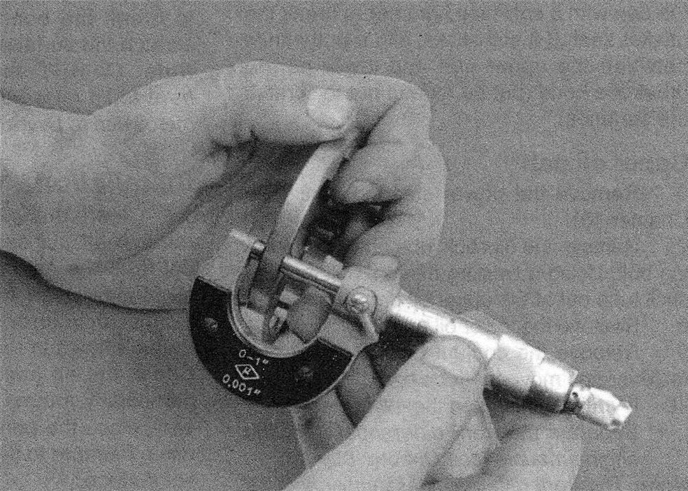
17. Measure the thickness of the outer rotor (see illustration). If the thickness is less than the value listed in this Chapter’s Specifications, the pump should be replaced.
12.17 Use a micrometer to measure the thickness of the outer rotor
18. Measure the thickness of the inner rotor. If the thickness is less than the value listed in this Chapter’s Specifications, the pump should be replaced.
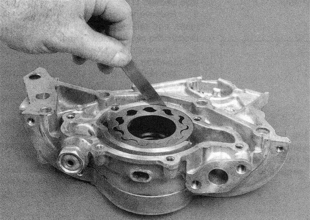
19. Insert the outer rotor into the oil pump housing and measure the clearance between the rotor and housing (see illustration). If the measurement is more than the maximum allowable clearance listed in this Chapter’s Specifications, the pump should be replaced.
12.19 Check the outer rotor-to-housing clearance with a feeler gauge
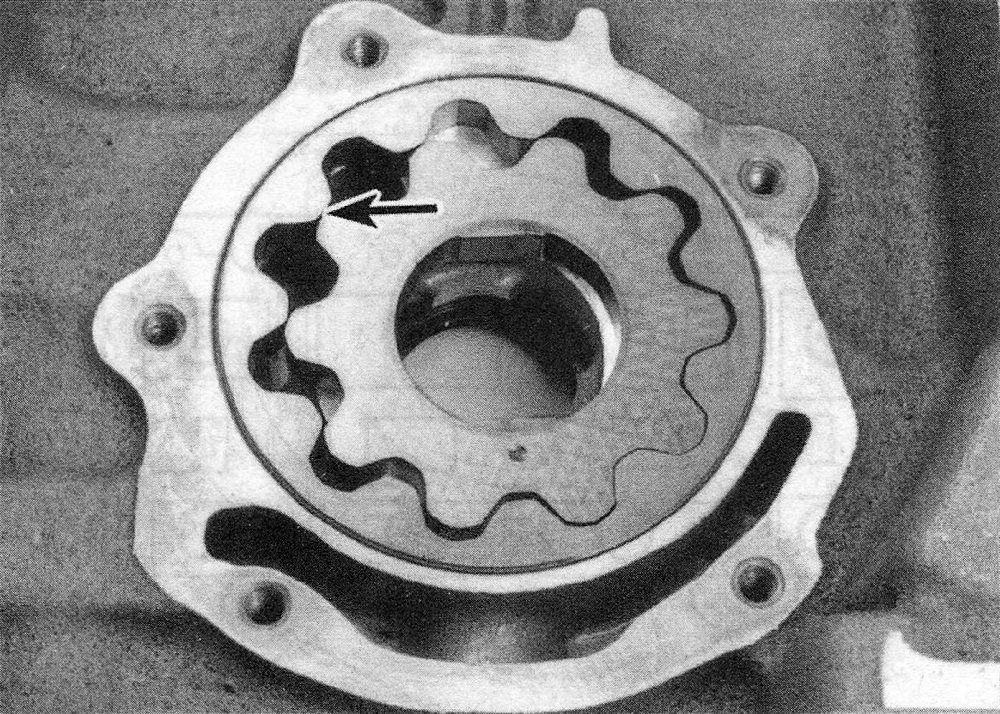
20. Install the inner rotor in the oil pump assembly and measure the clearance between the lobes on the inner and outer rotors (see illustration). If the clearance is more than the value listed in this Chapter’s Specifications, the pump should be replaced.
12.20 Check the clearance between the lobes of the inner and outer rotors
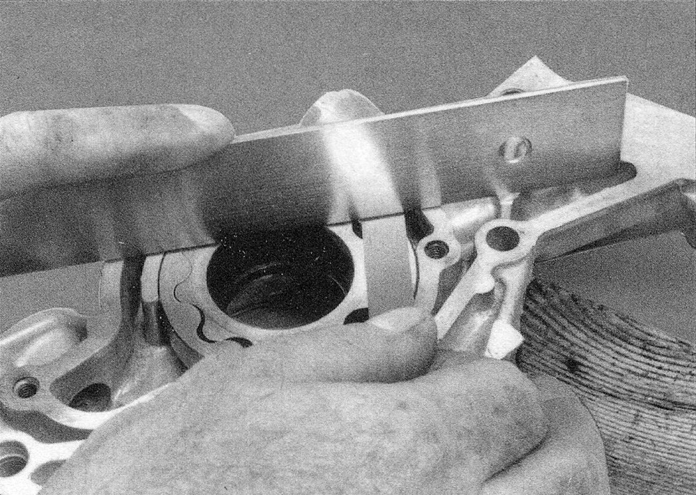
21. Place a straightedge across the face of the oil pump assembly (see illustration). If the clearance between the pump surface and the rotors is greater than the limit listed in this Chapter’s Specifications, the pump should be replaced.
12.21 Using a straightedge and feeler gauge, check the clearance between the surface of the oil pump cover and the rotors
Installation
22. Place the oil pump onto the engine block using the aligning dowels. Install the mounting bolts and tighten them to the torque listed in this Chapter’s Specifications.
23. Slide the oil pump chain tensioner onto the pivot, then push the tensioner back against the spring. Insert a 3 mm Allen wrench into the tensioner to hold it in place.
24. Place the oil pump timing chain gear into the chain, center it onto the oil pump shaft and install the T45 mounting bolt. Tighten the bolt to the torque listed in this Chapter’s Specifications.
Note: Make sure the gear is facing the same way as when it was removed (see Step 11). There are no timing marks on the pump gear or chain, and no timing is necessary.
25. Maneuver the oil pump solenoid into position and insert it through the block opening until it snaps in place.
26. Install the timing gear splash shield and bolts, then tighten the bolts to the torque listed in this Chapter’s Specifications.
27. The remainder of installation is the reverse of removal.
28. Refill the engine with oil and change the oil filter (see Tune-up and routine maintenance).