Intake manifolds – removal and installation
Warning: Wait until the engine is completely cool before beginning this procedure.
Removal
1. If you will be removing the lower intake manifold, relieve the fuel system pressure (see Fuel and exhaust systems – gasoline engines).
2. Disconnect the negative battery cable from the remote ground terminal (see Engine electrical systems).
3. If equipped, remove the engine cover.
Upper intake manifold
4. Disconnect the IAT sensor electrical connector then remove the top half of the air filter housing (see Tune-up and routine maintenance).
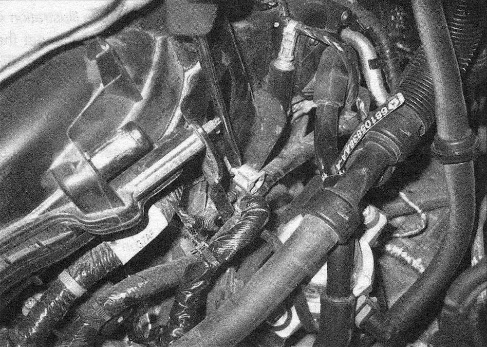
5. Remove the intake resonator (see illustration).
5.5 Loosen the resonator hose clamp, remove the attaching pin and remove the resonator
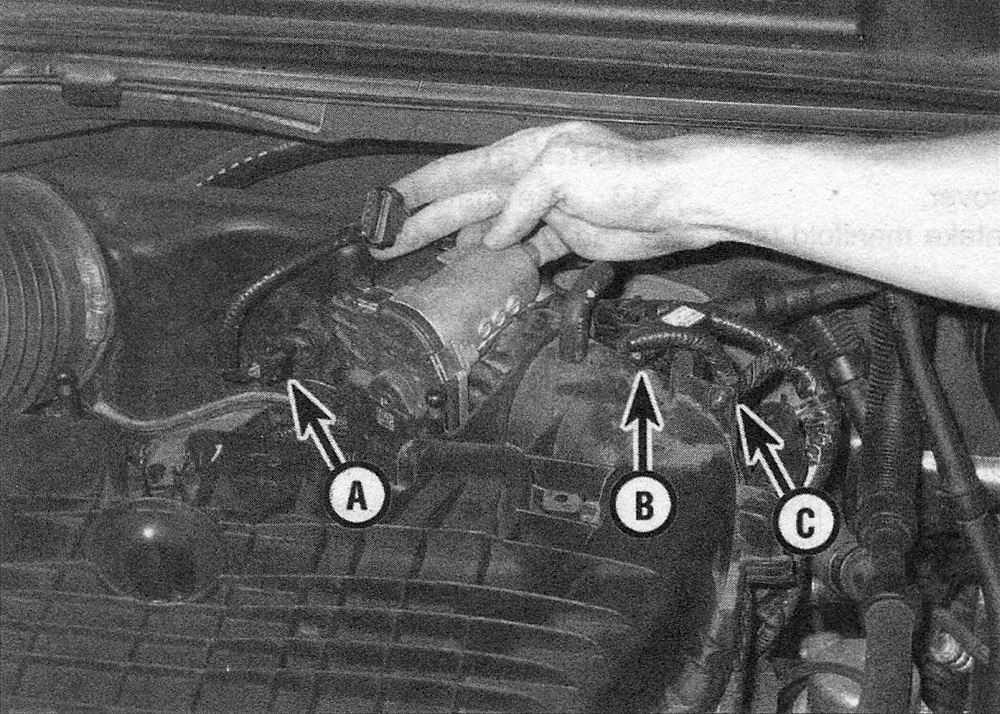
6. Disconnect the wiring harness from the MAP sensor and the Electronic Throttle Control (ETC) (see illustration).
5.6 Disconnect the ETC connectors (A), the MAP sensor (B) and the electrical harness (C) retainer
7. Disconnect the PCV valve hose (see Tune-up and routine maintenance), vapor purge hose and brake booster hoses.
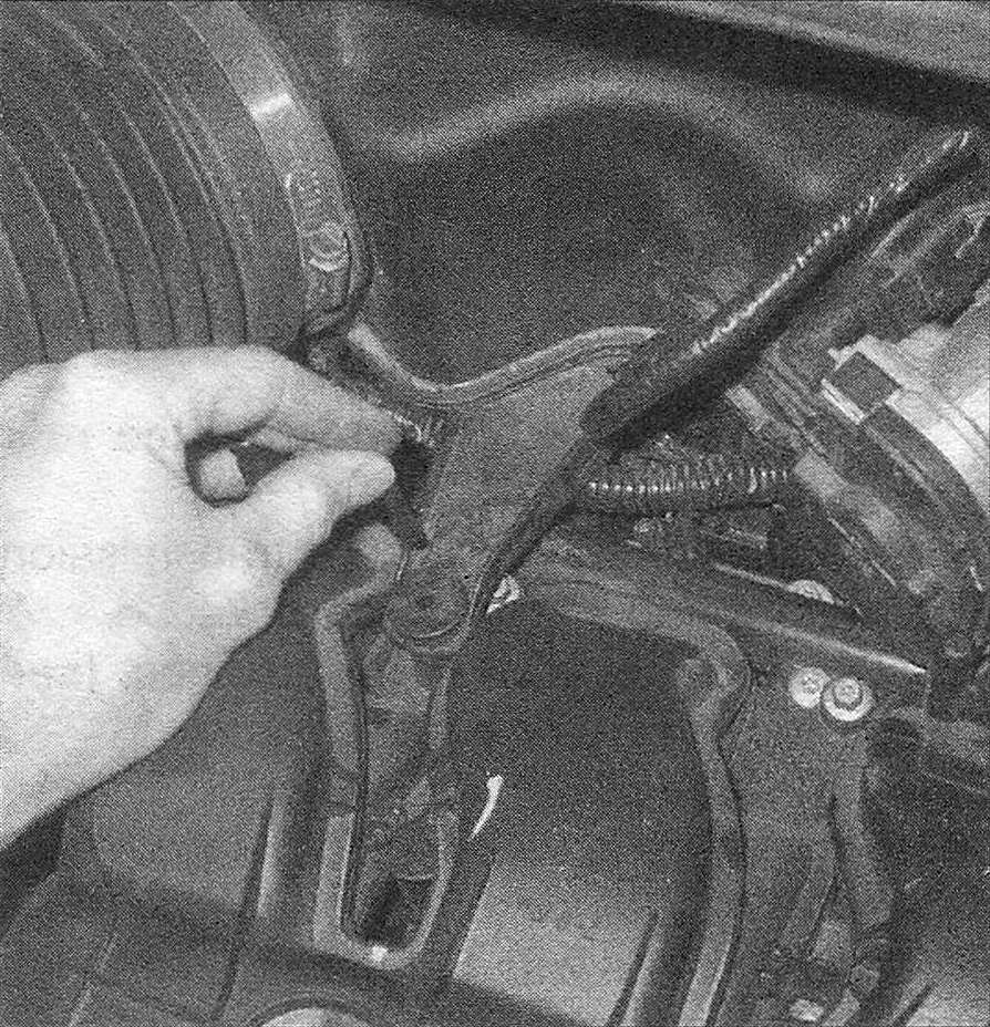
8. Disconnect the wiring harness retainers from the upper intake support bracket and the retainer from the stud bolt (see illustration).
5.8 Pry the wiring harness retainer off of the bracket stud
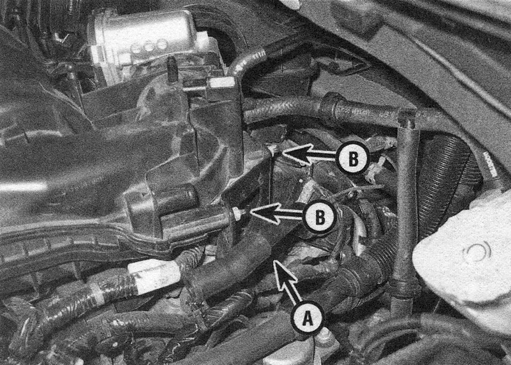
9. Remove the nuts and stud bolt, then remove the upper intake manifold bracket (see illustration).
5.9 Remove the stud bolt (A) and bracket nuts (B), and remove the bracket
10. Remove the brake booster hose-to-support bracket retainer.
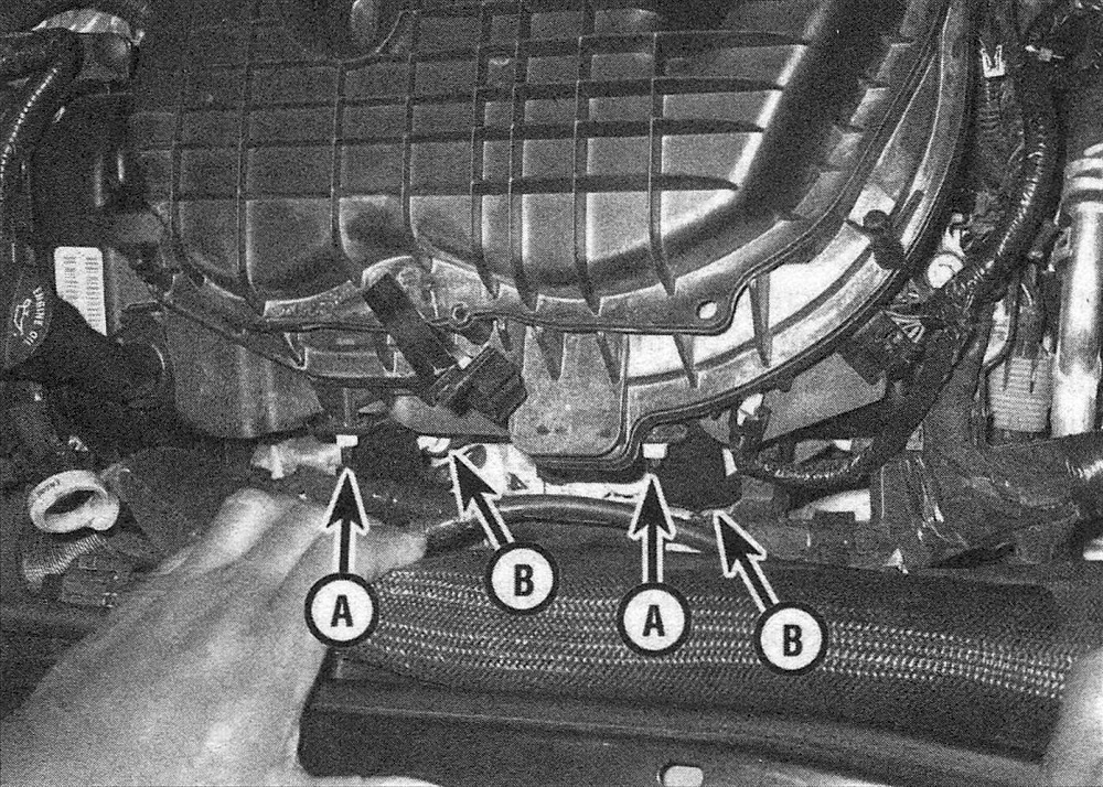
11. Remove the support bracket-to-upper manifold nuts (see illustration).
5.11 Remove the support bracket upper nuts (A), loosen the lower
12. Loosen the upper intake manifold bolts and remove the upper intake manifold (see illustration).
5.12 Location of the upper intake manifold bolts
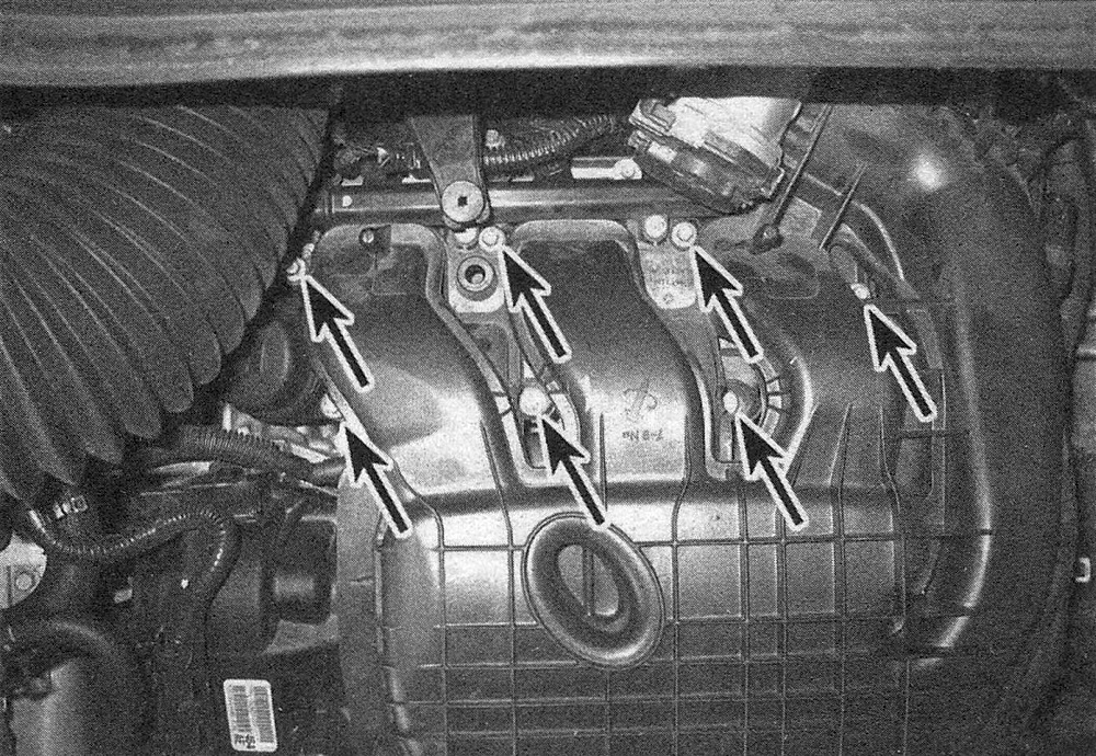
Note: The bolts are captive — don’t attempt to remove them from the manifold.
13. Discard the six upper-to-lower intake manifold seals, and cover the open intake ports to prevent debris from entering the engine.
14. If required, remove the insulator from the left valve cover (Valve covers – removal and installation).
Lower intake manifold
15. Remove the upper intake manifold (see Steps 4 through 14).
16. Disconnect the fuel line to the fuel rail (see Fuel and exhaust systems – gasoline engines).
17. Remove the fuel injectors and fuel rail (see Fuel and exhaust systems – gasoline engines).
Note: The lower intake manifold can be removed with the injectors and fuel rail in place, if desired. Be careful not to damage the fuel injectors once the manifold is removed.
18. Pry the wiring harness retainer from the end of the manifold and move the harness out of the way.
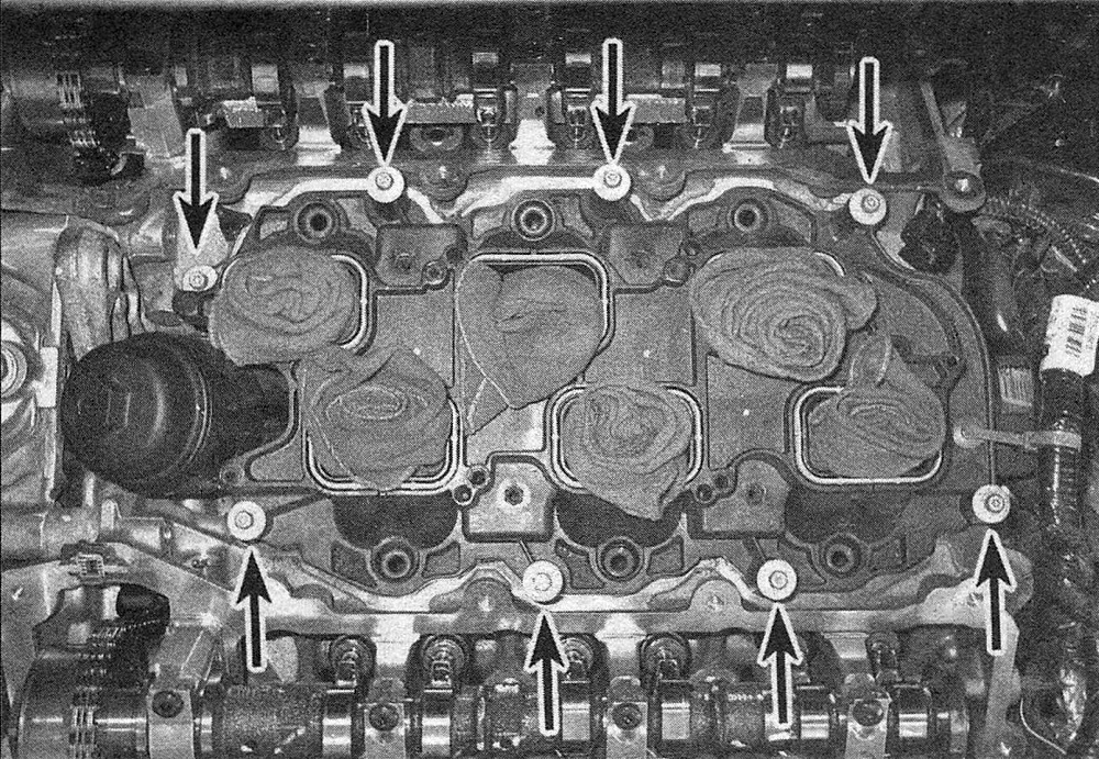
19. Remove the lower intake manifold bolts (see illustration), and remove the manifold from the cylinder heads.
5.19 Lower intake manifold bolt locations
20. Discard the six manifold-to-cylinder head seals.
Installation
Lower intake manifold
Note: The mating surfaces of the cylinder heads, cylinder block, and the intake manifold must be perfectly clean when the lower intake manifold is installed. Gasket removal solvents are available at most auto parts stores and may be helpful when removing old gasket material that’s stuck to the cylinder heads, cylinder block and lower intake manifold (the lower intake manifold is made of aluminum -aggressive scrapping can cause damage). Be sure to follow the instructions printed on the solvent container.
21. Use a gasket scraper to remove all traces of sealant and old gasket material, then clean the mating surfaces with brake system cleaner. If there’s old sealant or oil on the mating surfaces when the lower intake manifold is installed, oil or vacuum leaks may develop. Use a vacuum cleaner to remove gasket material that falls into the intake ports or the lifter valley.
22. If removed, install the fuel injectors and the fuel rail (see Fuel and exhaust systems – gasoline engines).
23. Install new intake manifold seals to the manifold.
Note: Remove any rags or towels used in the manifold ports.
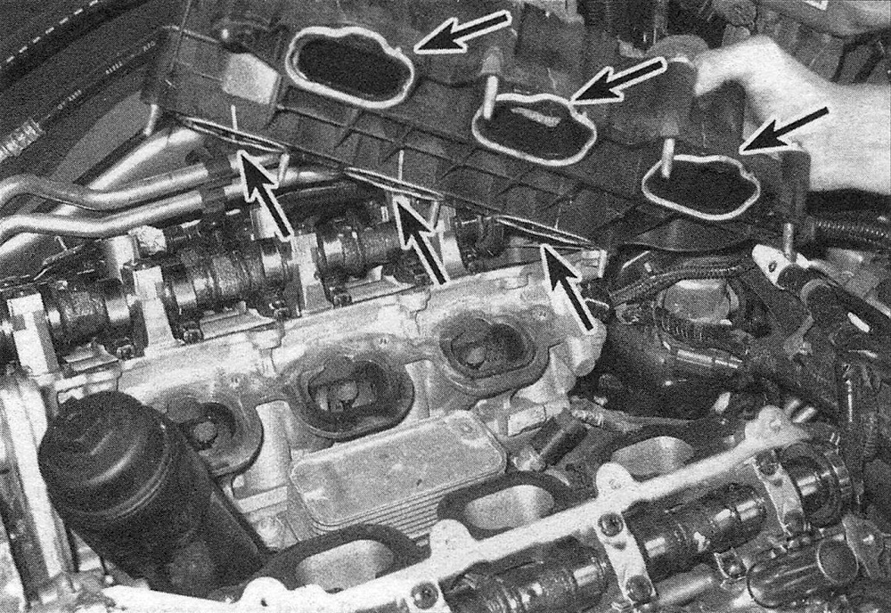
24. Carefully lower the lower intake manifold into place (see illustration) and install the mounting bolts finger-tight.
5.24 Install the manifold, making sure the new intake seals do not fall out of the manifold
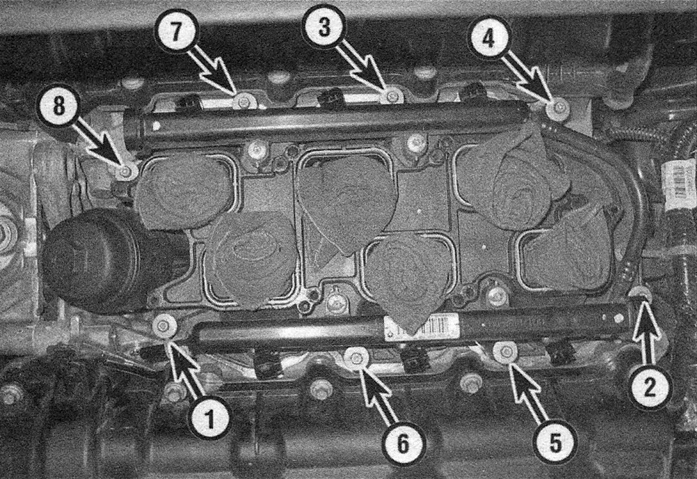
25. Tighten the mounting bolts in steps, following the tightening sequence (see illustration), to the torque listed in this Chapter’s Specifications.
5.25 Lower intake manifold bolt tightening sequence
26. Install the upper intake manifold.
Upper intake manifold
27. Check the condition of the rubber seals that are installed into each intake runner on the upper intake manifold. If they are damaged, replace them.
28. Place the insulator on the mounting pins, if removed.
29. Install the upper intake manifold onto the lower intake manifold while pulling the bolts up.
Note: The bolts are specially made for the composite material and should be turned slowly to prevent damage to the upper intake manifold.
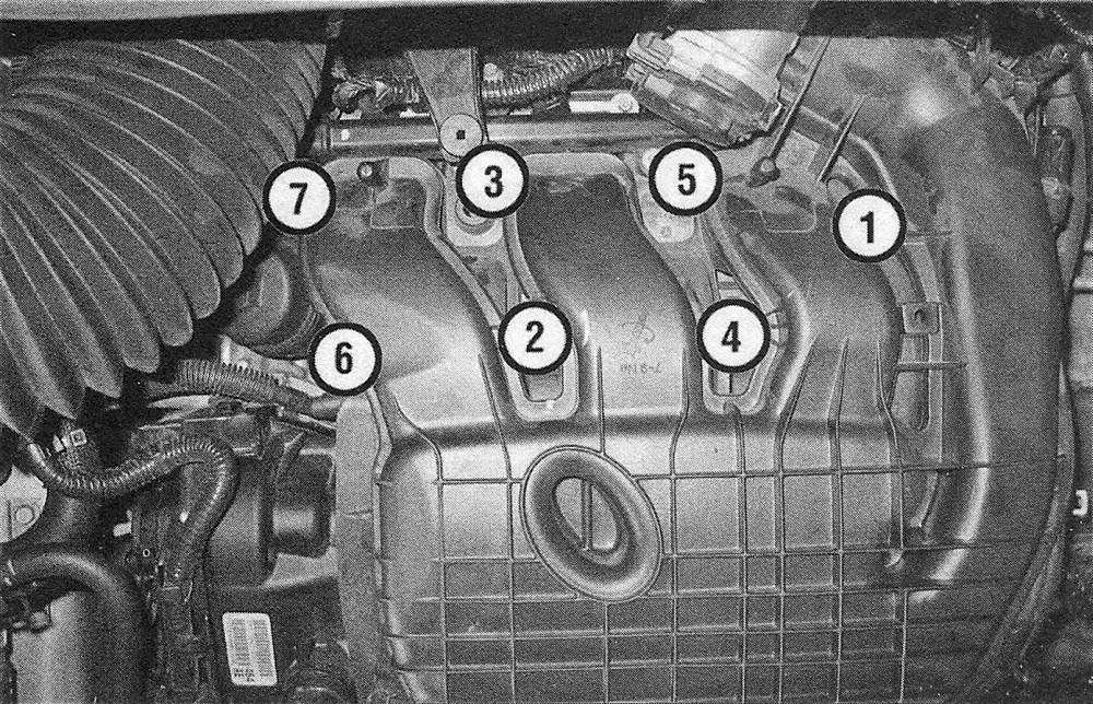
30. Tighten the mounting bolts in sequence (see illustration) to the torque listed in this Chapter’s Specifications.
5.30 Upper intake manifold bolt tightening sequence
31. The remainder of installation is the reverse of removal.