Cylinder heads – removal and installation
Warning: Wait until the engine is completely cool before beginning this procedure.
Removal
1. Relieve the fuel system pressure, then disconnect the cable from the negative terminal of the battery (see Engine electrical systems).
2. Drain the engine oil and coolant (see Tune-up and routine maintenance).
3. Remove the drivebelt (see Tune-up and routine maintenance) and the idler pulleys.
4. Remove the air filter housing and resonator (see Fuel and exhaust systems – gasoline engines).
5. Remove the intake manifolds (Intake manifolds – removal and installation).
6. Disconnect all wires and vacuum hoses from the cylinder heads. Label them to simplify reinstallation.
7. Disconnect the ignition coils and remove the spark plugs (see Tune-up and routine maintenance).
8. Remove the catalytic converter (s) (see Emissions and engine control systems).
9. Remove the valve covers (Valve covers – removal and installation).
10. Remove the crankshaft pulley (Crankshaft pulley – removal and installation).
11. Remove the oil pans (Oil pans – removal and installation).
12. If you’re working on the left cylinder head:
- Remove the alternator (see Engine electrical systems).
- Remove the transmission and oil dipstick tube fasteners and remove the oil dipstick tube from the oil pan.
- Unbolt the air conditioning compressor and support it out of the way (see Chapter Cooling, heating and air conditioning systems)
Warning: Do not disconnect the refrigerant lines.
- Disconnect the main engine harness connectors at the rear of the cylinder and move the harness and retainers out of the way.
13. If you’re working on the right cylinder head:
- Remove the heater core tube fasteners and move the tube away from the cylinder head.
14. Remove the timing chain cover (Timing chain cover, chain and sprockets – removal, inspection and installation).
15. Rotate the crankshaft clockwise and place the #1 piston at TDC on the exhaust stroke. When the crankshaft is at TDC, the dimple on the crankshaft will be in line with the line made where the bearing cap meets the engine block. The left cylinder bank cam phaser arrows should be pointing toward each other and be parallel with where the cylinder head and valve cover meets. The right side cam phaser arrows should point away from each other and the lines on the phasers should be pointing towards each other (see illustration 8.59).
16. Remove the timing chain for the cylinder head or, if both cylinder heads are being removed, remove both chains (Timing chain cover, chain and sprockets – removal, inspection and installation).
17. Remove the oil control valves from the cam phasers (sprockets) (Camshaft(s) – removal, inspection and installation).
18. Remove the timing chain tensioner and chain guides (Timing chain cover, chain and sprockets – removal, inspection and installation).
19. Remove the camshafts, rocker arms and lash adjusters (Camshaft(s) – removal, inspection and installation).
Caution: Once the valve covers are removed the magnetic timing wheels are exposed. The magnetic timing wheels on the camshafts must not come in contact with any type of magnet or magnetic field. If contact is made the timing wheels will have to be replaced (Camshaft(s) – removal, inspection and installation).
Note: Keep the rocker arms and lash adjusters in order so that they can be installed in their original locations.
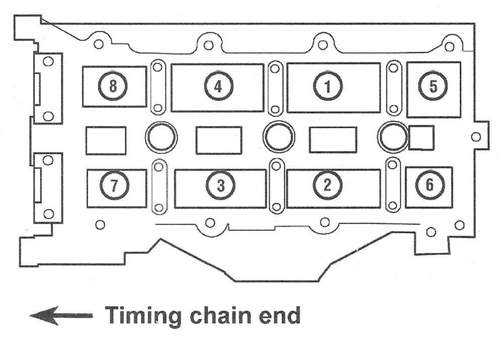
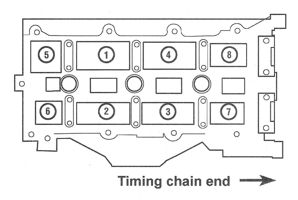
20. Loosen the cylinder head bolts in the reverse of the tightening sequence (see illus trations 10.29a and 10.29b).
21. Lift the cylinder head off the block. If resistance is felt, dislodge the cylinder head by striking it with a wood block and hammer. If prying is required, pry only on a casting protrusion – be very careful not to damage the cylinder head or block!
Caution: Do not set the cylinder head on its gasket side; the sealing surface can be easily damaged.
22. Have the cylinder head inspected and serviced by a qualified automotive machine shop.
Installation
23. The mating surfaces of each cylinder head and the engine block must be perfectly clean when the cylinder head is installed.
24. Carefully use a gasket scraper to remove all traces of carbon and old gasket material, then clean the mating surfaces with brake system cleaner. If there’s oil on the mating surfaces when the cylinder head is installed, the gasket may not seal correctly and leaks may develop.
25. When working on the engine block, it’s a good idea to cover the lifter valley with shop rags to keep debris out of the engine. Use a shop rag or vacuum cleaner to remove any debris that falls into the cylinders.
26. Check the engine block and cylinder head mating surfaces for nicks, deep scratches, and other damage. If damage is slight, it can be removed with a file; if it’s excessive, machining may be the only alternative.
27. Position the new gasket over the dowel pins in the engine block. Some gaskets are marked TOP or FRONT to ensure correct installation.
28. Carefully position the cylinder head on the engine block without disturbing the gasket.
29. Install NEW cylinder head bolts and tighten them in the recommended sequence (see illustrations) to the torque steps listed in this Chapter’s Specifications.
10.29a Left side cylinder head bolt TIGHTENING sequence
10.29b Right side cylinder head bolt TIGHTENING sequence
Caution: Do not use a torque wrench for steps requiring additional rotation or turns; apply a paint mark to the bolt head or use a torque-angle gauge (available at most auto parts stores) and a socket and breaker bar.
30. The remainder of installation is the reverse of removal.
31. Change the engine oil and filter (see Tune-up and routine maintenance).
32. Refill the cooling system (see Tune-up and routine maintenance). Start the engine and check for leaks and proper operation.