Camshaft(s) – removal, inspection and installation
Caution: The timing system is complex, and severe engine damage will occur if you make any mistakes. Do not attempt this procedure unless you are highly experienced with this type of repair. If you are at all unsure of your abilities, be sure to consult an expert. Double-check all your work and be sure everything is correct before you attempt to start the engine. Caution: Once the valve covers are removed, the magnetic timing wheels are exposed. The magnetic timing wheels on the camshafts must not come in contact with any type of magnet or magnetic field. If contact is made, the timing wheels will need to be replaced. Note: The timing chain for each camshaft can be removed from the camshafts individually, without removing all the timing chains, using the tools outlined in this Section. If the tools are not available, the timing chain cover and all chains will need to be removed before the camshafts can be removed (Timing chain cover, chain and sprockets – removal, inspection and installation).
Removal
1. Disconnect the cable from the negative terminal of the battery (see Engine electrical systems).
2. Drain the engine oil and coolant, then remove the drivebelt (see Tune-up and routine maintenance).
3. Remove the air filter housing and resonator (see illustration 5.5).
4. Remove the intake manifolds (Intake manifolds – removal and installation).
5. Disconnect all wires and vacuum hoses from the cylinder heads. Label them to simplify reinstallation.
6. Label the ignition coils to simplify reinstallation then disconnect and remove the ignition coils (see Tune-up and routine maintenance).
7. Remove the spark plugs (see Tune-up and routine maintenance).
8. Remove the valve covers (Valve covers – removal and installation).
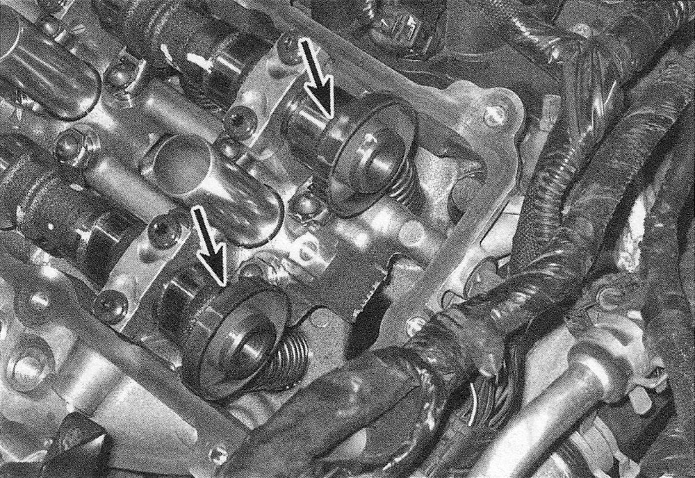
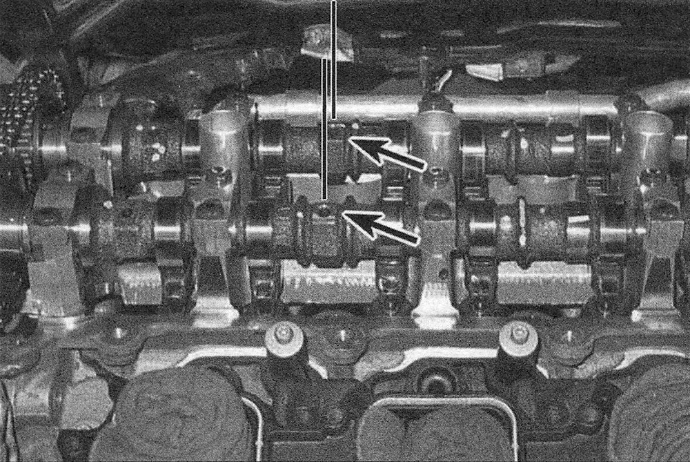
9. Once the valve covers are removed, the magnetic timing wheels are exposed (see illustration). The magnetic timing wheels on the camshafts must not come in contact with any type of magnet or magnetic field. If contact is made, the timing wheels will need to be replaced.
9.9 Location of the magnetic timing wheels
10. Rotate the crankshaft clockwise and place the #1 piston at TDC on the exhaust stroke. On the left side camshaft phaser, the machined scribe lines should be facing away from each other, and the arrows should be pointing towards each other in a parallel line with the gasket surface of the cylinder head. On the right side camshaft phaser, the arrows should be facing away from each other, and the machined scribe lines should be pointing towards each other in a parallel line with the gaskets surface of the cylinder head (see illustrations).
9.10a With the engine at TDC #1, the left camshaft phaser scribe marks (A) should be pointing away from each other, the arrow marks (B) should be pointing towards each other in a straight line and that line should be parallel with the cylinder head surface
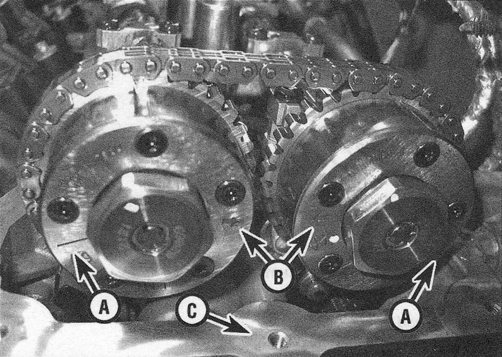
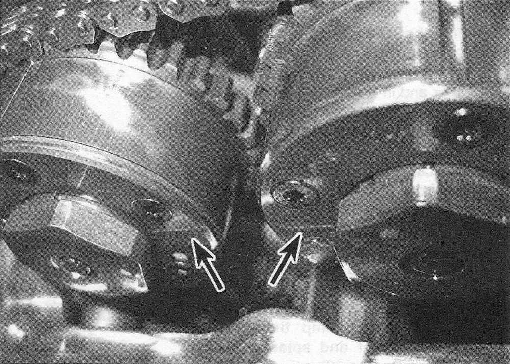
9.10b The right phaser scribe marks should be pointing towards each other in a straight line (and that line should be parallel with the cylinder head surface)
11. Using a permanent marker or paint, mark the camshaft phasers to the timing chains for reinstallation.
12. Working from the top of the timing chain cover, insert special tool #10200-3 down the side of the tensioner to the access hole on the side of the tensioner. Working through the small hole in the side of the tensioner, lift and hold the pawl off of the rack of the plunger in the tensioner. Slide chain holding tool #10200-1 between the cylinder head and the back side of the chain against the chain guide, forcing the rack and plunger back into the tensioner body.
Caution: The chain holding tool must remain in place while the phasers are removed or the timing chain will fall off into the timing chain cover.
13. Slide camshaft phaser lock tool #10202-1 (right side) or 10202-2 (left side), from the front, between the two camshaft phasers, towards the chain.
Note: It may be necessary to rotate the intake camshaft a few degrees using a wrench on the camshaft flat when installing the phaser lock tool.
14. Using a large wrench on the camshaft flats and a socket and ratchet on the oil control valves, loosen, then remove each of the oil control valves from the phaser end of the camshaft.
15. At the same time, carefully slide both the intake and exhaust phaser (with the phaser lock securely between them) forward until they are off the end of the camshafts.
Caution: Do not remove the phaser lock or try to disassemble the phasers.
16. Using the alignment holes in the camshaft as a reference point, slowly rotate both camshafts counterclockwise approximately 30-degrees Before Top Dead Center (BTDC). In this position, the camshafts are in a neutral or no load position.
Note: The camshaft bearing caps are marked with a number and letter code; » 11 » is for the number one Intake camshaft bearing cap. The notch on the caps should always be installed towards the front.
17. Loosen the camshaft bearing cap bolts in the reverse of the tightening sequence (see illustration 9.28).
18. Remove the camshaft bearing caps and carefully lift the camshafts from the cylinder head.
19. Mark the rocker arms so they can be installed in their original locations, then remove them.
20. Mark the hydraulic lash adjusters so they can be installed in their original locations, then remove them from the cylinder head.
Inspection
21. Check the camshaft bearing surfaces for pitting, score marks, galling, and abnormal wear. If the bearing surfaces are damaged, the cylinder head will have to be replaced.
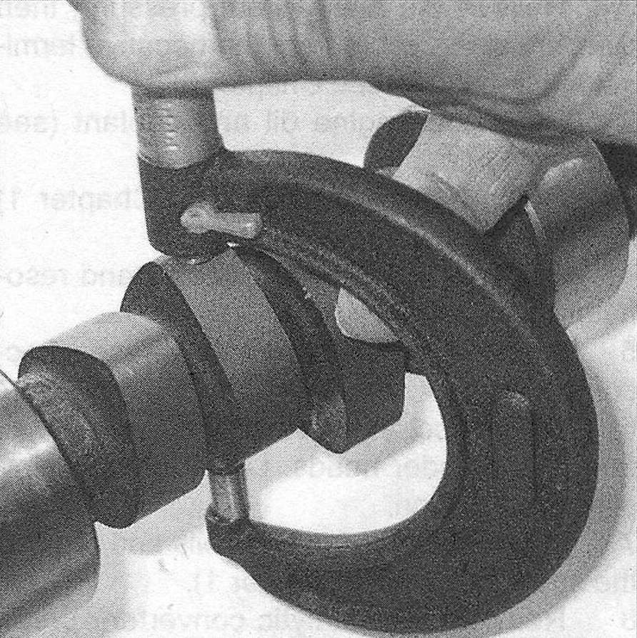
22. Compare the camshaft lobe height by measuring each lobe with a micrometer (see illustration). Measure each of the intake lobes and record the measurements and relative positions. Then measure each of the exhaust lobes and record the measurements and relative positions also. This will let you compare all of the intake lobes to one another and all of the exhaust lobes to one another. If the difference between the lobes exceeds 0.005 inch, the camshaft should be replaced. Do not compare intake lobe heights to exhaust lobe heights as lobe lift may be different. Only compare intake lobes to intake lobes and exhaust lobes to exhaust lobes for this comparison.
9.22 Use a micrometer to measure cam lobe height
23. Check the rocker arms and shafts for abnormal wear, pits, galling, score marks, and rough spots. Don’t attempt to restore rocker arms by grinding the pad surfaces. Replace defective parts.
Installation
Caution: Before starting the engine, carefully rotate the crankshaft by hand through at least two full revolutions (use a socket and breaker bar on the crankshaft pulley center bolt). If you feel any resistance, STOP! There is something wrong – most likely, valves are contacting the pistons. You must find the problem before proceeding.
24. Dip the hydraulic lash adjusters in clean engine oil and install them into their original locations.
25. Apply moly-base grease or engine assembly lube to the rocker arm contact points and rollers and install them into their original locations.
26. Lubricate the camshaft bearing journals and lobes with moly-base grease or engine assembly lube, then install them carefully in the cylinder head about 30-degrees before (counterclockwise of) TDC. Don’t scratch the bearing surfaces with the cam lobes!
Caution: Do not rotate the camshafts more than a few degrees to prevent the valves from contacting the pistons.
27. Install the camshaft bearing caps, then install the mounting bolts and finger tighten them.
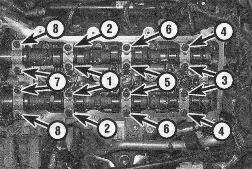
28. Tighten the bearing caps in sequence (see illustration) to the torque listed in this Chapter’s Specifications.
9.28 Camshaft bearing cap tightening sequence — left side shown, right side is identical
29. Rotate the camshafts clockwise 30-degrees, and verify the alignment holes in the camshafts are in the 12 o’clock (pointing straight up) or neutral position (see illustration).
9.29 Locate the alignment holes on the camshafts and make sure they are in the neutral position (pointing straight up) — right side shown, left side is identical
30. Carefully slide both the intake and exhaust phaser (with the phaser lock tool securely between them) onto the camshafts and verify the marks are aligned.
31. Install the oil control valves onto the camshaft phasers and install the bolts, then tighten the bolts to the torque listed in this Chapter’s Specifications. Remove the chain holding tool and release the tensioner plunger.
Caution: Be sure to prevent the camshafts from turning by holding the camshaft with a large wrench on the camshaft flats.
32. Slowly rotate the engine two complete turns (720-degrees) and verify the alignment marks are correct (see illustrations 9.10a and 9.10b).
33. The remainder of installation is the reverse of removal.