Pickup box
The pickup box has many features designed for utility and convenience.
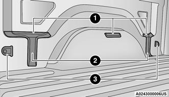
Pickup Box Features
1 — Upper Load Floor Indents
2 — Bulk Head Dividers
3 — Cleats
NOTE:
If you are installing a Toolbox, Ladder Rack or Headache Rack at the front of the pickup box, you must use Mopar® Box Reinforcement Brackets that are available from an authorized dealer.
You can carry wide building materials (sheets of plywood, etc.) by building a raised load floor. Place lumber across the box in the indentations provided above the wheel housings and in the bulkhead dividers to form the floor.
⚠ WARNING!
● The pickup box is intended for load carrying purposes only, not for passengers, who should sit in seats and use seat belts.
● Care should always be exercised when operating a vehicle with unrestrained cargo.
Vehicle speeds may need to be reduced.
Severe turns or rough roads may cause shifting or bouncing of the cargo that may result in vehicle damage. If wide building materials are to be frequently carried, the installation of a support is recommended. This will restrain the cargo and transfer the load to the pickup box floor.
● If you wish to carry more than 600 lb (272 kg) of material suspended above the wheelhouse, supports must be installed to transfer the weight of the load to the pickup box floor or vehicle damage may result. The use of proper supports will permit loading up to the rated payload.
● Unrestrained cargo may be thrown forward in an accident causing serious or fatal injury.
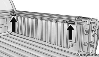
There are stampings in the sheet metal on the inner side bulkheads of the box in front of and behind both wheel housings. Place wooden boards across the box from side to side to create separate load compartments in the pickup box.
There are four tie-down cleats bolted to the lower sides of the pickup box that can sustain loads up to 1000 lb (450 kg) total.
BED RAIL TIE-DOWN SYSTEM — IF EQUIPPED
CAUTION!
The maximum load per cleat should not exceed 250 lb (113 kg) and the angle of the load on each cleat should not exceed 45 degrees above horizontal, or damage to the cleat or cleat rail may occur.
NOTE:
This feature is available for vehicles both equipped, or not equipped, with a RamBox.
There are two adjustable cleats on each side of the bed that can be used to assist in securing cargo.
Adjustable Cleats
Each cleat must be located and tightened down in one of the detents, along either rail, in order to keep cargo properly secure.
To move the cleat to any position on the rail, turn the nut counterclockwise, approximately three turns. Then pull out on the cleat and slide it to the detent nearest the desired location. Make sure the cleat is seated in the detent and tighten the nut.
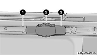
Adjustable Cleat Assembly
1 — Utility Rail Detent
2 — Cleat Retainer Nut
3 — Utility Rail Cleat
Cleat Removal (Standard Box Rail)
To remove the cleats from the utility rail, slide the cleat forward to access the cut out at the end of the box rail, then remove the cleat.
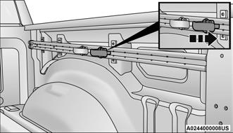
Slide Cleat Forward To Remove
Cleat Removal (With Tonneau Cover)
To remove the cleats from the utility rail, remove the end cap screw located in the center of the end cap, using a #T30 Torx head driver. Remove the end cap and slide the cleat off the end of the rail.
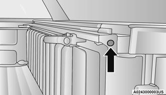
End Cap Screw Location If Equipped With Tonneau Cover
Cleat Removal (Without Tonneau Cover)
Remove the end cap by pushing upward on the release button located beneath the end cap while pulling the cap away from the rail. The cleat can now be removed by sliding it off the end of the rail.
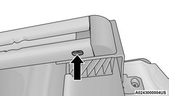
End Cap Release Button If Not Equipped With Tonneau Cover
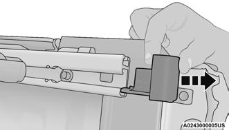
Pull End Cap Away From Rail